西门子SIPLACE S-27 HM用户手册.pdf - 第145页
User Manual SIPLAC E S-27 HM 6 Component han dling Software vers ion SR.503.xx 07/2003 US Edition 6.4 Component trolley 145 6.4 Component trolley 6.4.1 Structure The com ponent tr olley cons ists esse ntially of a chassi…
6 Component handling User Manual SIPLACE S-27 HM
6.3 Setting up the feeders Software version SR.503.xx07/2003 US Edition
144
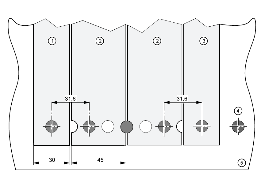
Fig. 6.3 - 1 Inserting 30 or 45 mm wide feeders on the component table
(1) Feeder, 30 mm wide
(2) Feeder, 45 mm wide
(3) Feeder, 30 mm wide
(4) Centering ball
(5) Component feeder table
User Manual SIPLACE S-27 HM 6 Component handling
Software version SR.503.xx 07/2003 US Edition 6.4 Component trolley
145
6.4 Component trolley
6.4.1 Structure
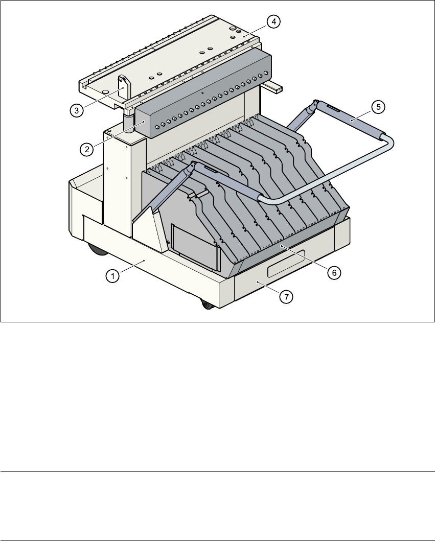
The component trolley consists essentially of a chassis, a component feeder table on which the
feeder is mounted, a communication unit, a tape container and a waste container.
Fig. 6.4 - 1 Component trolley
(1) Component trolley
(2) Communication unit
(3) Control button for raising the component feeder table
(4) Component feeder table
(5) Handle for locking and lowering the component feeder table
(6) Tape container
(7) Waste tape container
NOTE ON OPERATIONAL SAFETY
All component trolleys or matrix tray changers must be docked on the machine in order to oper-
ate it. If they are not, the machine stays in EMERGENCY STOP status. The placement process
is interrupted.
6 Component handling User Manual SIPLACE S-27 HM
6.4 Component trolley Software version SR.503.xx07/2003 US Edition
146
Docking and undocking the component trolley is described in Section 5.9, page 124 onwards.
6.4.2 Tape container
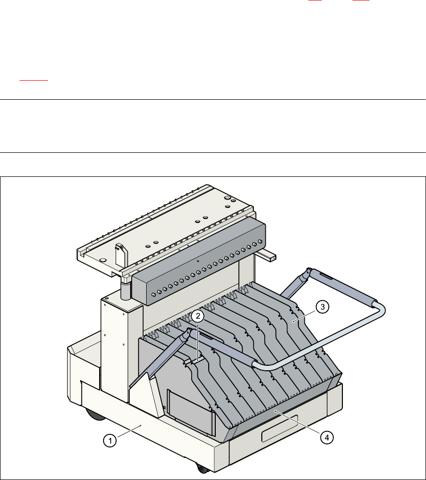
Reels up to 19" in diameter may be used. Insert the spindles into the dividing plates as shown in
Fig. 6.4 - 2
.
PLEASE NOTE 6
We recommend that you use spindles if the tape reel diameter exceeds 7". This will ensure that
the feeders operate reliably. 6
6
Fig. 6.4 - 2 Component trolley with tape container
(1) Component trolley
(2) Spindles
(3) Dividing plate
(4) Tape container