西门子SIPLACE S-27 HM用户手册.pdf - 第127页
User Manual SIPLAC E S-27 HM 5 O perator, Line engineer, Service engineer Software vers ion SR.503.xx 07/2003 US Edition 5.9 Docking and undocking the component trolley 127 5.9.3 Docking the component trolley W A RNING 5…
5 Operator, Line engineer, Service engineer User Manual SIPLACE S-27 HM
5.9 Docking and undocking the component trolley Software version SR.503.xx07/2003 US Edition
126
(7) Fold-down bracket
(8) Holes for the centering pins
(9) Centering pins
(10) Contact surfaces for the slide rails of the component trolley
(11) Horizontal tensioners
(12) Movable cover that ensures that the power supply and control cables are plugged in and
removed in the correct order.
5
5.9.2 Undocking the component trolley
Æ
Click on the STOP PROCESSING PCB icon in the MAIN VIEW menu.
Æ The PCB in progress will be completed. The icons of the SINGLE FUNCTIONS menu will then
be activated.
Æ Click on the desired SINGLE FUNCTIONS GANTRY X icon (gantry 1 or 2).
Æ Click on the GANTRY FUNCTIONS icon.
Æ From this menu, click on the GO TO SET-UP POSITION button.
Æ The selected placement head will move across the PCB transport to prevent it being damaged
when the component trolley is changed.
Æ Open protective cover of the selected gantry.
Æ Open the side screens.
Æ Open the horizontal tensioners (item 11).
Æ Pull the two actuating tubes (item 6) towards you at the same time and lift up the bracket
(item 7). Thus you will lock the raised component table bed in its top end position.
WARNING DANGER OF CRUSHING 5
Never reach into the gaps between the feeders and the used tape channel while the com-
ponent trolley table bed is being lowered. 5
Æ Hold down the button (item 5) for raising the component table bed (item 4) until the component
table bed reaches its top end position.
Æ Unplug the component trolley power cable (item 2).
Æ Move the cover (item 12) sideways until you can unplug the control cable (item 1).
Æ Unplug the component table control cable (item 1).
Æ Disconnect the compressed air supply (item 3).
Æ Remove the component trolley.
User Manual SIPLACE S-27 HM 5 Operator, Line engineer, Service engineer
Software version SR.503.xx 07/2003 US Edition 5.9 Docking and undocking the component trolley
127
5.9.3 Docking the component trolley
WARNING 5
Check that the placement head is outside the range of the component trolley. 5
CAUTION 5
When docking the component trolley, ensure that the table bed is in its top end position and the
bracket (item 7) is folded up. 5
Æ Cut off the empty tapes for the feeders.
Æ Make sure that the contact surface (item 10) for the component table bed is clean.
Æ CAREFULLY push the component trolley into the placement system.
Æ Connect the compressed air supply (item 3).
Æ Plug in the control cable (item 1).
Æ Move the cover (item 12) over the control cable plug to expose the power supply socket.
Æ Plug in the power cable (item 2) for the component trolley.
Æ Pull the two actuating tubes (item 6) towards you at the same time and then lower the trolley
bracket (item 7) in order to be able to lower the component table bed.
Æ Check that the centering holes in the component trolley table bed lie precisely over the center-
ing pins of the placement system.
Æ Hold down the button (item 5) until the component trolley table bed reaches its top end position.
WARNING DANGER OF CRUSHING 5
Never reach into the gaps between the feeders and the used tape channel while the com-
ponent trolley table bed is being lowered. 5
Æ Release the button. The component trolley table bed will descend.
Æ Ensure that the centering pins engage in the centering holes in the component trolley table bed
and that the component trolley table bed is fully lowered.
Æ Lock the two horizontal tensioners (item 11).
Æ Close the side screens and protective cover.
Æ Press the Start button to start the placement system.
5 Operator, Line engineer, Service engineer User Manual SIPLACE S-27 HM
5.10 Operating status indicator lamp Software version SR.503.xx07/2003 US Edition
128
5.10 Operating status indicator lamp
The indicator lamp is used to signal operating statuses and malfunctions of the placement system.
5.10.1 Description of the functions
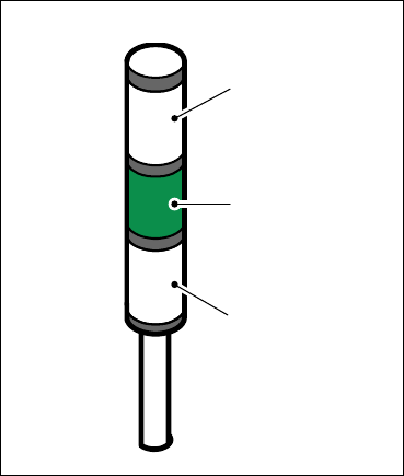
Fig. 5.10 - 1 Operating status indicator lamp
L1 Fault indicator lamp (white, right)
L2 Operating status lamp (green)
L3 Fault indicator lamp (white, left)
5.10.2 General operating statuses
– Operating status lamp (green) on continuously
The placement system is in service.
– Operating status lamp (green) flashes
The placement system is waiting for a PCB on the input belt or the placement system is waiting
until the output belt is free.
– Right white fault indicator lamp L1 flashes
One or more tracks are empty on the right-hand side of the placement system. The placement
system continues to place any remaining components.
L1
L2
L3