西门子SIPLACE S-27 HM用户手册.pdf - 第185页
User Manual SIPLAC E S-27 HM 7 Station extensions Software vers ion SR.503.xx 07/ 2003 US Edition 7.5 Ceramic substrate centering 185 – Blue oblique l ighting: In most c ases, this can be used to greatly i mprove the con…
7 Station extensions User Manual SIPLACE S-27 HM
7.5 Ceramic substrate centering Software version SR.503.xx07/2003 US Edition
184
7.5.5 Optical centering with the multi-color PCB camera
7.5.5.1 General
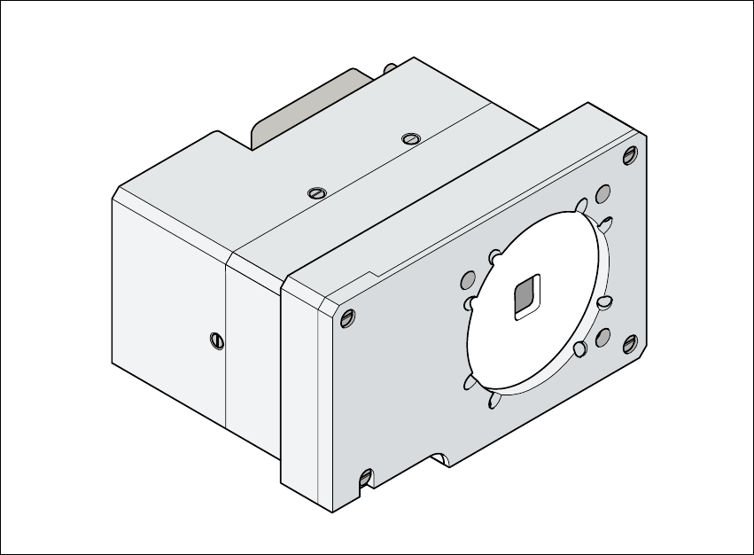
As an option, a multicolor PCB camera can be installed in place of the sub-gantry camera. The
multicolor PCB camera offers four different types of illumination. This greatly increases fiducial de-
tection and thus the centering accuracy.
7
Fig. 7.5 - 3 Multi-color PCB camera
7
7.5.5.2 Types of illumination for the multicolor PCB camera
The following types of illumination can be selected on the multicolor PCB camera:
– Standard lighting
This mixture of white and infrared lighting can be used to detect a broad range of fiducials. The
image contrast can be improved by varying the illumination, thus optimizing the centering of
different fiducials.
– White lighting
This type of illumination is used for standard PCBs with tinned fiducials.

User Manual SIPLACE S-27 HM 7 Station extensions
Software version SR.503.xx 07/2003 US Edition 7.5 Ceramic substrate centering
185
– Blue oblique lighting:
In most cases, this can be used to greatly improve the contrast with bright fiducials on a light
base material, such as ceramic or CEM (c
omposite electrochemical materials). Fiducials cov-
ered with solder resist can also be detected better on a light background.
– Infrared lighting
This type of illumination is particularly useful for fiducials that are covered with solder resist or
for fiducials on flex materials. It is also sometimes possible to improve detection of silver/plat-
inum fiducials on ceramic. This should be tested by carrying out a test centering or placement
run.

7 Station extensions User Manual SIPLACE S-27 HM
7.6 Fine calibration Software version SR.503.xx07/2003 US Edition
186
7.6 Fine calibration
7.6.1 Overview
Fine calibration involves measuring the machine’s placement offset and determining the required
correction from this value. The ‘Fine calibration’ measuring program is integrated into the SIT-
EST program, and a detailed description of the measuring procedure is given in the ‘Fine calibra-
tion’ instructions (article no. 00191655-01).
CAUTION
The SITEST program is password-protected. It must only be called up and used by
SIEMENSDEMATIC engineers or appropriately trained personnel. 7
7.6.2 System requirements
The following system requirements must be fulfilled in order to use the fine calibration program:
Machine type S-27 HM
Station computer software version 503.xx or later
SITEST version 503.xx or later
PLEASE NOTE: 7
The fine calibration can only be carried out with the 12-segment Collect&Place head. 7
7.6.3 Measuring equipment and tools
The following are supplied as standard:
– Mapping plate (glass plate in a metal frame)
– Double-sided transparent adhesive film
– Lighting unit
– CERAM components in the feeder for the 12-segment Collect&Place head