西门子SIPLACE S-27 HM用户手册.pdf - 第125页
User Manual SIPLAC E S-27 HM 5 O perator, Line engineer, Service engineer Software vers ion SR.503.xx 07/2003 US Edition 5.9 Docking and undocking the component trolley 125 Fig. 5.9 - 2 Doc king or undocking the componen…
5 Operator, Line engineer, Service engineer User Manual SIPLACE S-27 HM
5.9 Docking and undocking the component trolley Software version SR.503.xx07/2003 US Edition
124
5.9 Docking and undocking the component trolley
5.9.1 Safety instructions on docking and undocking the component trolley
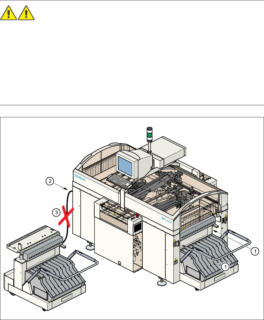
WARNING 5
Æ Never reach into the gap between the component trolley and the placement system frame
(item 1).
Æ Always check that the component trolley is docked on the placement system before connecting
or disconnecting the power cable for the component trolley at the socket on the placement sys-
tem (item 2).
Æ NEVER connect the connecting cable for the component trolley to the socket on the placement
system and then operate the component trolley outside the machine via the compressed air
control unit (item 3).
5
Fig. 5.9 - 1 Safety instructions on the component trolley
User Manual SIPLACE S-27 HM 5 Operator, Line engineer, Service engineer
Software version SR.503.xx 07/2003 US Edition 5.9 Docking and undocking the component trolley
125
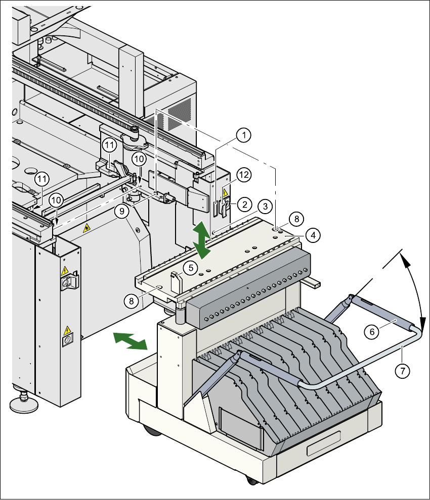
Fig. 5.9 - 2 Docking or undocking the component trolley
(1) Communication interface connector
(2) Power supply connector for the component trolley
(3) Compressed air connection
(4) Component table bed
(5) Button for raising and lowering the component table bed
(6) Actuating tube
5 Operator, Line engineer, Service engineer User Manual SIPLACE S-27 HM
5.9 Docking and undocking the component trolley Software version SR.503.xx07/2003 US Edition
126
(7) Fold-down bracket
(8) Holes for the centering pins
(9) Centering pins
(10) Contact surfaces for the slide rails of the component trolley
(11) Horizontal tensioners
(12) Movable cover that ensures that the power supply and control cables are plugged in and
removed in the correct order.
5
5.9.2 Undocking the component trolley
Æ
Click on the STOP PROCESSING PCB icon in the MAIN VIEW menu.
Æ The PCB in progress will be completed. The icons of the SINGLE FUNCTIONS menu will then
be activated.
Æ Click on the desired SINGLE FUNCTIONS GANTRY X icon (gantry 1 or 2).
Æ Click on the GANTRY FUNCTIONS icon.
Æ From this menu, click on the GO TO SET-UP POSITION button.
Æ The selected placement head will move across the PCB transport to prevent it being damaged
when the component trolley is changed.
Æ Open protective cover of the selected gantry.
Æ Open the side screens.
Æ Open the horizontal tensioners (item 11).
Æ Pull the two actuating tubes (item 6) towards you at the same time and lift up the bracket
(item 7). Thus you will lock the raised component table bed in its top end position.
WARNING DANGER OF CRUSHING 5
Never reach into the gaps between the feeders and the used tape channel while the com-
ponent trolley table bed is being lowered. 5
Æ Hold down the button (item 5) for raising the component table bed (item 4) until the component
table bed reaches its top end position.
Æ Unplug the component trolley power cable (item 2).
Æ Move the cover (item 12) sideways until you can unplug the control cable (item 1).
Æ Unplug the component table control cable (item 1).
Æ Disconnect the compressed air supply (item 3).
Æ Remove the component trolley.