西门子SIPLACE S-27 HM用户手册.pdf - 第182页
7 Station extensions User Manual S IPLACE S-27 H M 7.5 Ceramic substrate centering Software version SR.503.xx07/2003 US E dition 182 7.5.4 Fiduc ial shape re commendation fo r ceramic substrates The cont rast betw een th…

User Manual SIPLACE S-27 HM 7 Station extensions
Software version SR.503.xx 07/2003 US Edition 7.5 Ceramic substrate centering
181
7.5.3 Technical data
7
7
Substrate format 50 mm x 50 mm to 100 mm x 180
mm
Substrate thickness 0.5 mm to 1.5 mm
Substrate model Unscribed (without problems)
Scribed (requires testing)
Support on the conveyor 2.5 mm
Optical centering: field of view of the PCB vision module
Type of illumination for light pastes:
Type of illumination for dark pastes and close
spacing to adjacent structures (> 1 mm):
5.7 mm x 5.7 mm
PCB camera (standard)
Multicolor camera (option)
(4 illumination levels to be selected)
Fiducial criteria See PCB vision module position
detection
Mechanical centering:
X/Y centering accuracy ± 0.07 mm / 4 sigma
PCB underside clearance 12 mm
Compressed air connection 0.55 MPa (5.5 bar)
7 Station extensions User Manual SIPLACE S-27 HM
7.5 Ceramic substrate centering Software version SR.503.xx07/2003 US Edition
182
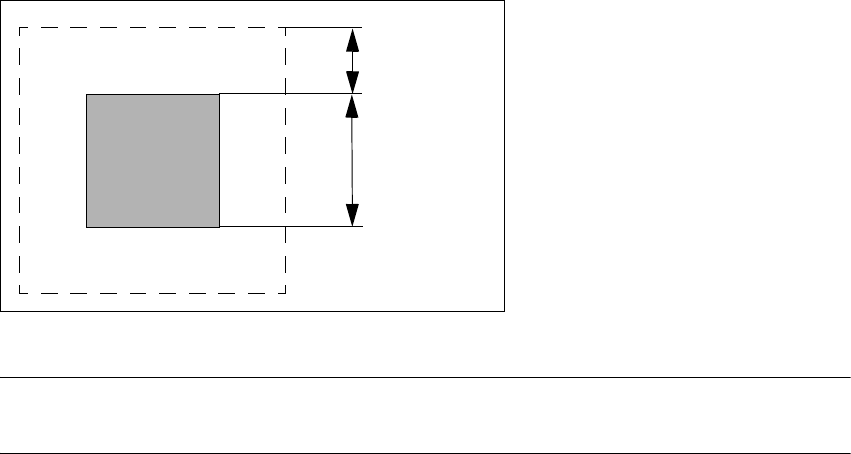
7.5.4 Fiducial shape recommendation for ceramic substrates
The contrast between the carrier package material and the circuit-board conductor layer is gen-
erally very small with ceramic substrates. The fiducials must therefore be selected with regard to
certain criteria concerning the fiducial shape and structure. Recommended fiducial shapes and
structures are given below.
7.5.4.1 Fiducial shape
We recommend a rectangle or square with an edge length of > 1 mm, and a clearance of
>0.5mm.
7
Fig. 7.5 - 2 Recommended fiducial shape
PLEASE NOTE
Single crosses are also suitable, but they take up more space. 7
0.5 mm
1.0 mm

User Manual SIPLACE S-27 HM 7 Station extensions
Software version SR.503.xx 07/2003 US Edition 7.5 Ceramic substrate centering
183
7.5.4.2 Fiducial structure
7
7
7
Recommendation 1
Fiducial structure Black resistive paste as the background. Conductive paste printed on it
as the fiducial.
Recommendation Background 0.75 mm larger than the fiducial on all sides.
Method of illumination Normal light
Advantage Good contrast; good sharpness;
Reference Circuit-board conductor layer
Assessment This combination gives the best results. Highly recommended.
Recommendation 2
Fiducial structure Fiducial made from circuit-board conductor material, e.g. 6119, and
overprinted with passivated glass 4330.
Method of illumination Oblique light
Advantage No additional steps required
Reference Circuit-board conductor layer
Assessment Fiducials are less sharp than for recommendation 1. Recommended.
Recommendation 3
Fiducial structure Fiducials made from circuit-board conductor layer against a free ceramic
background.
Method of illumination Oblique or normal light (depending on the paste)
Advantage No additional steps required
Reference Circuit-board conductor layer
Note Fiducials are less sharp than for recommendation 2.
The fiducial image depends on the surrounding free surface. It may be
necessary to teach every circuit separately.
Assessment Recommended under certain conditions.