西门子SIPLACE S-27 HM用户手册.pdf - 第56页
2 Operational safety User Manual SIPLACE S-27 HM 2.5 Safety equipment Software v ersion SR.503.xx07/2003 US Edition 56 K1 or K2 is trig gered if any of the se functi ons fail . The mains voltage t o the heavy current tra…
User Manual SIPLACE S-27 HM 2 Operational safety
Software version SR.503.xx 07/2003 US Edition 2.5 Safety equipment
55
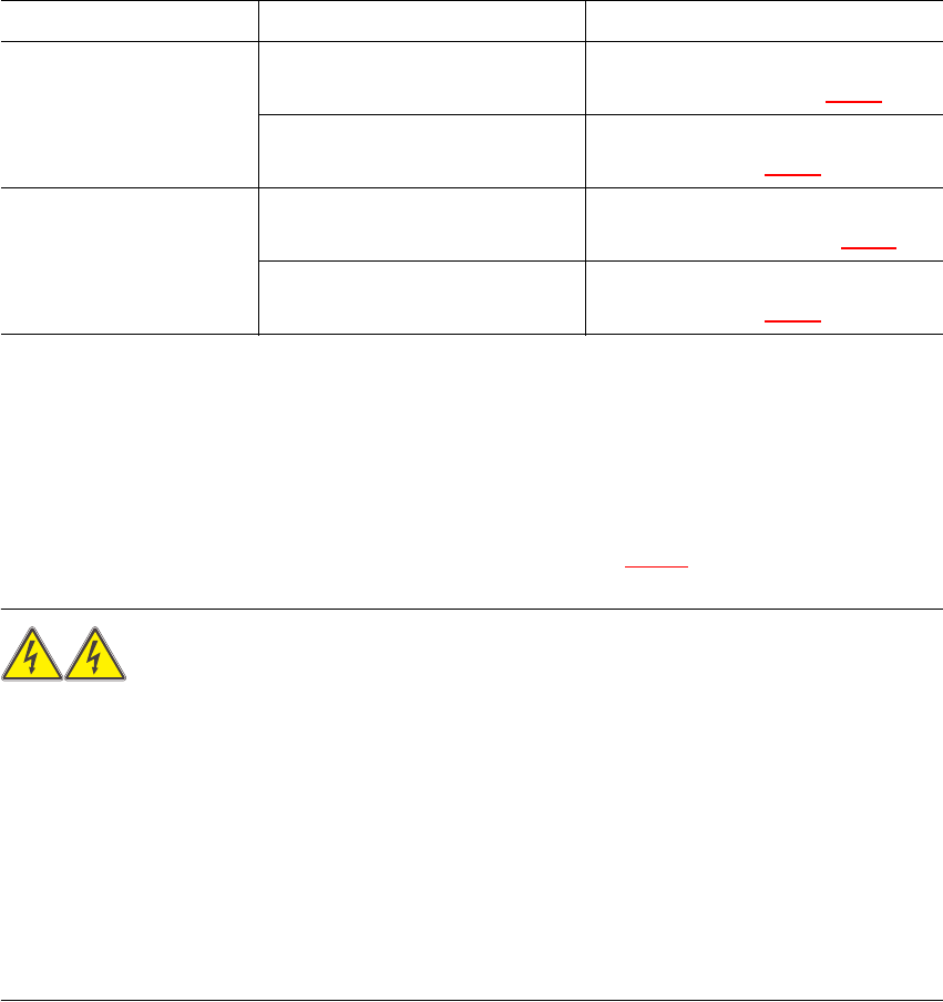
2.5.3.2 Status messages and the action required
The following displays may appear in placement mode. If they appear, carry out the action spec-
ified in the third column.
2
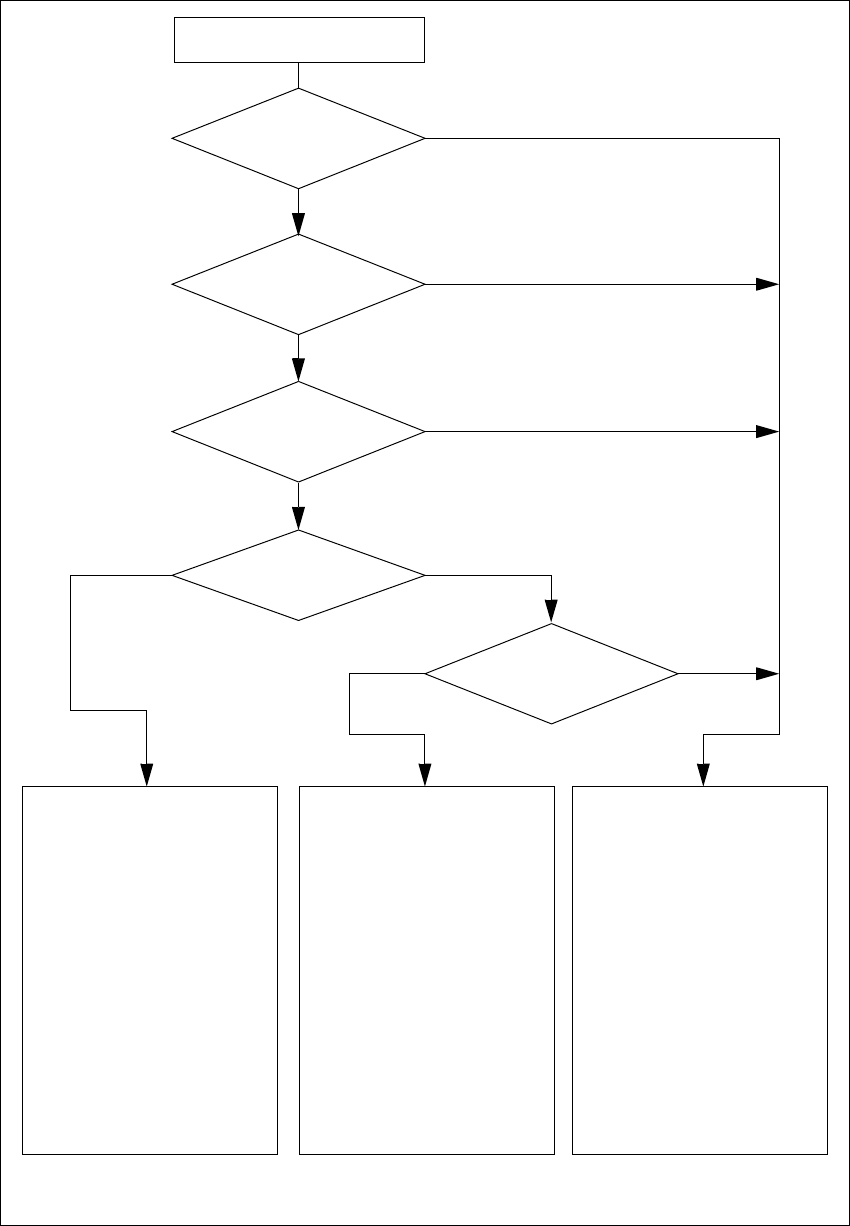
2.5.4 Safety circuits
The SIPLACE automatic placement system has two separate safety circuits which are monitored
by protective contactor combinations K1 and K2. Both protective contactor combinations are
incorporated into the power supply (see items 14 and 15 in Fig. 2.5 - 4
).
WARNING
Automatic placement systems from the SIPLACE family are powered with 3 x 400 VAC (3 x 208
VAC for the U.S.A. version) ± 5 %, 50/60 Hz main power voltage.
This means that some parts of the system carry potentially lethal voltages - even when switched
off at the main power switch. Death, serious injury or considerable damage may result if these au-
tomatic placement systems are handled incorrectly.
Always follow the applicable accident prevention and DIN regulations (particularly EN 60204,
part 1) and the applicable regulations in your own country.
The guard over the power supply must ONLY be opened by appropriately qualified and trained
personnel. 2
Protective contactor combinations K1 and K2 monitor the following circuits:
K1: EMERGENCY STOP circuit, safety circuits for the component trolleys or waffle-pack
changer, protective cover switches and the enable software signal
K2: EMERGENCY STOP circuit, K1 protective contactor combination, software enable signal
and key switch
Status Display on screen Action required
EMERGENCY STOP
button pressed
Emergency stop pressed ...
Machine stopped. Release button
Release the pressed emergency stop
button (item 3 or 4 in Fig. 2.5 - 4
)
Press start button Press the white start button
(item 2 or 5 in Fig. 2.5 - 4
)
Protective cover open Close the cover Close the protective cover
(item 9, 10, 11 or 12 in Fig. 2.5 - 4
)
Press start button Press the white start button
(item 2 or 5 in Fig. 2.5 - 4
)
Tab. 2.5 - 1 Screen display when the emergency stop button is pressed or the protective cover is open
2 Operational safety User Manual SIPLACE S-27 HM
2.5 Safety equipment Software version SR.503.xx07/2003 US Edition
56
K1 or K2 is triggered if any of these functions fail. The mains voltage to the heavy current trans-
former that supplies the gantry axis motors will be interrupted. The voltage to the star-type motor
for the Collect&Place head is reduced from 70 V to 10 V. The DP and DR axes of the placement
heads continue to be supplied with 30 V. The next diagram illustrates the various statuses of K1
and K2 and their effects on the axes and the PCB conveyor components.
User Manual SIPLACE S-27 HM 2 Operational safety
Software version SR.503.xx 07/2003 US Edition 2.5 Safety equipment
57
Fig. 2.5 - 5 Safety circuits
Start button pressed
Emerg. stop button
pressed?
Protective cover open ?
Key switch
closed (position I)?
No
Component
table safety circuit
interrupted?
Yes
No
No
Yes
Yes
No
Active
K1 *) Yes
K2 *) Yes
Voltage
Y axis 155 V
X axis 155 V
Star axis 70 V
DP axis 30 V
Z axis 30 V
Active
PCB conveyor Yes
Lifting table Yes
PCB clamping Yes
Width adjustment Yes
Laser light barrier Yes
Tape cutter Yes
Yes
Active
K1 *) No
K2 *) Yes
Voltage
Y axis 0 V
X axis 0 V
Star axis 10 V
DP axis 30 V
Z axis 30 V
Active
PCB conveyor Yes
Lifting table No
PCB clamping No
Width adjustment Yes
Laser light barrier No
Tape cutter No
Active
K1 *) No
K2 *) No
Voltage
Y axis 0 V
X axis 0 V
Star axis 10 V
DP axis 30 V
Z axis 30 V
Active
PCB conveyor No
Lifting table No
PCB clamping No
Width adjustment No
Laser light barrier No
Tape cutter No
*) K1, K2 protective contactor combination
Compressed
air min. 0.55 MPa
(5.5 bar)?
Yes
No