AltaPail II Bulk Melters Product Manual.pdf - 第40页
Installation 3-9 Part 1121836_03 E 11/2014 Nordson Corporation Installing Inputs and Out puts The inputs a nd outputs are used to ex change data wit h the customer's production equipment and cont rol hardware such a…
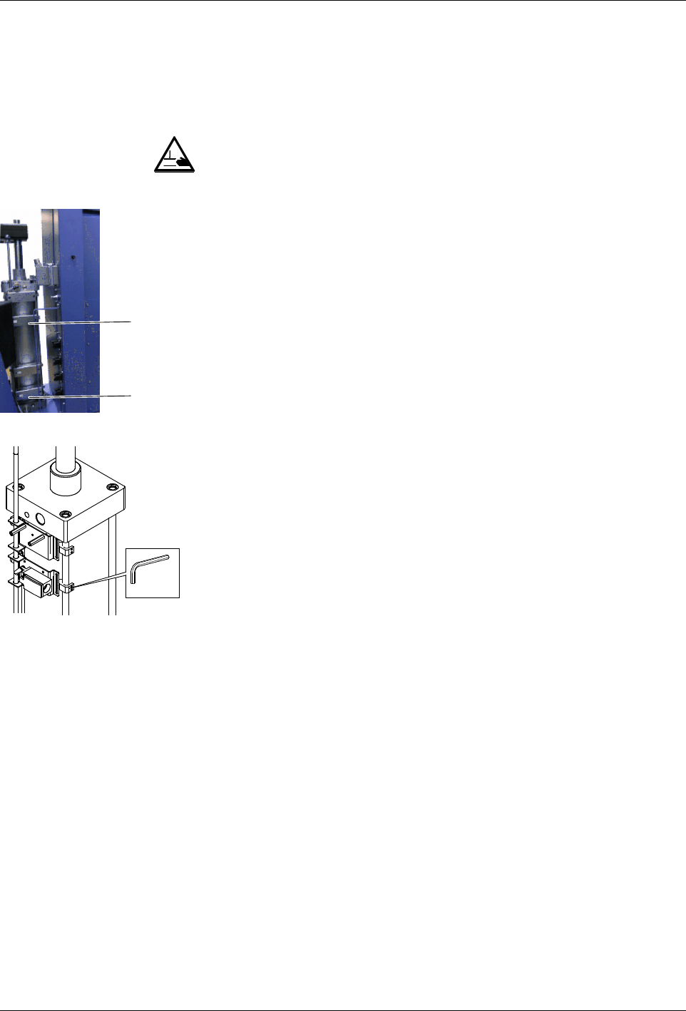
2
1
2mm
Installation
3-8
Part 1121836_03
E 11/2014 Nordson Corporation
Adapting the Bulk Melter to the Container Used
Platen Position: Adjusting Switches
WARNING: Risk of squash! Make sure that switch 1 is not actuated until the
platen is inside the container.
A switch rod activates the two switches (1 and 2) one after the other,
triggering the following switching functions:
S
Switching functions when lowering:
S
Switches from two-hand lowering mode to normal lowering mode
when the platen sealing ring is completely submerged in the container
(switch 1)
S
Activates the Container empty indication (switch 2).
S
Switching functions when raising:
S
Switches off container aeration (switch 1).

Installation
3-9
Part 1121836_03
E 11/2014 Nordson Corporation
Installing Inputs and Outputs
The inputs and outputs are used to exchange data with the customer's
production equipment and control hardware such as a PLC.
1. A female quick connector (24 positions + PE) is located on the melter
side panel. Route a signal cable from the control equipment to the melter
through a male quick connector (24 positions + PE). The male quick
connector has a M25 strain relief to fasten the signal cable. I/O connector
designation: -10X21 Function: transmits the digital input/output signals
and gear-to-line signal between the parent machine and the Nordson
melter provide 24VDC from internal melter.
NOTE: Use a signal cable suitable for NEC class1 remote control and
signaling circuits. To reduce the possibility of electrical shorting, route the
cable so that it does not touch nearby circuit boards.
2. Connect each pair of input and output wires to the appropriate terminals
on I/O connector. Refer to table below for the terminal numbers that
correspond to each input.
Figure 3-2 Back of electrical cabinet
Connecting Line Speed Voltage
To use automatic mode, a signal generator, such as an encoder, must be
provided by the customer and installed to measure the production line speed.
The pump controller accepts an analog 0-10 V
DC
input signal. Connect to
coupler component -190U1; make sure the polarity is correct - refer to wiring
diagram.

Installation
3-10
Part 1121836_03
E 11/2014 Nordson Corporation
Terminal Block XL1
Item Description Control
Options
Terminals Notes
1 Standard
input 1
Notes A
and B
-10X21:8,-10X21:9 Input activated with 10 - 30 VDC. The input is not
polarity sensitive.
2 Standard
input 2
Note A
-10X21:10,-10X21:11
Input activated with 10 - 30 VDC. The input is not
polarity sensitive.
3
Standard
input 3
Note A
-10X21:12,-10X21:13
Input activated with 10 - 30 VDC. The input is not
polarity sensitive.
4 Standard
input 4
Note A
-10X21:7,-10X21:14
Input activated with 10 - 30 VDC. The input is not
polarity sensitive.
5 Standard
output 1
Note C
-10X21:1,-10X21:2
The output is a electromechanical relay contact
rated for 2 Amps at 240 VAC or 30 VDC.
6 Standard
output 2
Note C
-10X21:3,-10X21:4
The output is a electromechanical relay contact
rated for 2 Amps at 240 VAC or 30 VDC.
7 Standard
output 3
Note C
-10X21:5,-10X21:6
The output is a electromechanical relay contact
rated for 2 Amps at 240 VAC or 30 VDC.
8 gear-to-line
0-10V input
-10X21:15,-10X21:16
Connect the positive wire to -17X21:15. Connect
the negative wire to -17X21:16. Note that the
negative input is connected to chassis (PE).
9 Pump
remote
on/off
-10X21:17,-10X21:18
Input activated with 18 - 30 VDC. The input is not
polarity sensitive. Activating the input will turn on
the motor when the remote control feature is
enabled from the user interface.
10 Pump drive
running
-10X21:19,-10X21:20
Electromechanical relay contact that indicates
motor is running when closed. Contact rated for
1.5 Amps at 240 VAC or 30 VDC.
11 24VDC
Output
-10X21:21,-10X21:22
24 V - 17x21:21
0 V - 17x21:22
Contact rating max: 24 VDC/1A
NOTE A: Input Options: Disabled, Standby, Heater Control, Pump Control and External Zone 1-8. Automatic
Standby is only available for input #1.
B: Automatic Standby is only available for input #1.
C: Output Options: Disabled, Ready, Ready-Pump On, Fault, Pail Low, Alert and Service Reminder.
Removing Bulk Melter
1. Remove the container.
2. When the bulk melter will not be used for longer periods of time, purge
with cleaning agent if necessary. Refer to page 8-6, Purging with
Cleaning Agent.
3. Wipe off sealing ring and clean melting plate. Refer to page 8-6, Cleaning
Melting Plate.
4. Disconnect all lines to the bulk melter, and allow bulk melter to cool.
Bulk Melter Disposal
When your Nordson product has exhausted its purpose and/or is no longer
needed, dispose of it properly according to local regulations.