AltaPail II Bulk Melters Product Manual.pdf - 第58页
About the Touch Screen Display and U ser Interface 5 -7 Part 1121836_03 E 1 1/2014 Nordson Corporation External Zones - Hose and Applicator/Hand Gun From the Home Display , you can view the s tate and s tatus for each ho…
About the Touch Screen Display and User Interface
5-6
Part 1121836_03
E 11/2014 Nordson Corporation
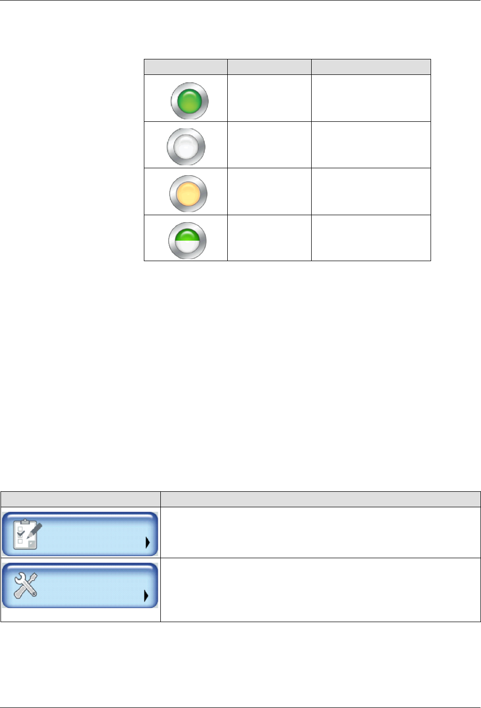
About the Pump Indicator Button
The following table describes what the Pump button color represents.
Button Color Description
Green On
White Off
Orange Auto Pump enabled
Half green, Half
white
Remote Pump Control
setup and enabled
NOTES:
S
The Master Pump and Heater Controls automatically switch Off, when the
melter is in a Fault condition.
S
You must wait until the melter status indicates Ready\OK before you can
manually or remotely switch On the master Pump Control.
S
You can enable the Auto Pump option, which automatically switches On
the Master Pump Control when the melter status indicates Ready\OK.
S
The Pump Control button uses different colors to indicate Remote Control
and if the Auto Pump option is enabled. Refer to the table below for more
information. Refer to Enabling and Disabling Auto Pump for more
information.
About Accessing Basic and Advanced Melter Settings
NOTE: Refer to the Quick Reference Card for a detailed menu map.
Touch To configure …
Settings
Temperature, Pump, Input/Output settings as well as to define Ready
Delay and Standby automatic time-based settings.
System
Password, Formats, Date/Time, Display settings and Language
preferences. You can also define daily Scheduled heat and standby
events and access Administrative functions such as System and
Password Reset and access the event log.
About the Touch Screen Display and User Interface
5-7
Part 1121836_03
E 11/2014 Nordson Corporation
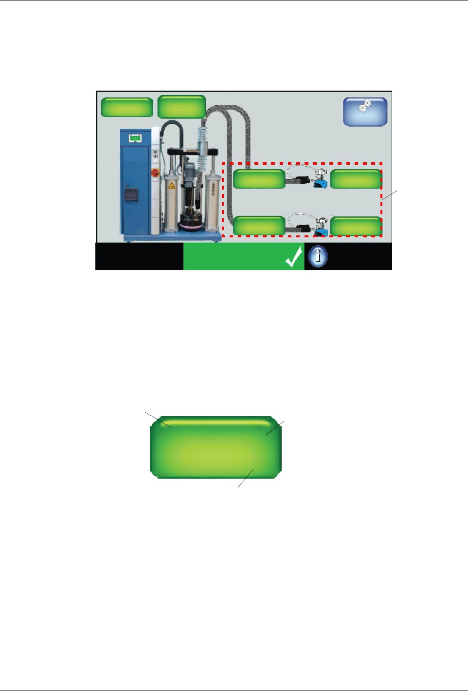
External Zones - Hose and Applicator/Hand Gun
From the Home Display, you can view the state and status for each hose
and applicator zone.
System Status:
Ready/OK
Platen
176_C
176_C
Pump
GTL
32 RPM
Zone 1A
Pump: On
Heaters: On
Password: Disabled
Recipes:
Nothing Loaded
176_C
Zone 1B
176_C
Zone 2A
176_C
Zone 2B
External
Zones
Master
Controls
You can also touch an external zone to:
S
Enable\disable hose and/or applicator zones.
S
Create or modify hose and applicator zone names.
S
Define individual zone set point temperatures.
S
Modify default channel associations (PID).
Name of hose or applicator
Real-time temperature indicator
Zone 1A
145_
__
_ C
←
←
The external zone pair has
been configured to be con-
trolled from a remote loca-
tion.
Figure 5-3 Zone button details
NOTE:
S
External zones include hoses, applicators and optional air heaters.
S
Default name consists of the word Zone, and its corresponding
channel number. Typically, these are pairs, where the letter A
represents a hose and the letter B represents the applicator. You can
change these default channel associations.
S
At least one external zone is required for normal operation.
About the Touch Screen Display and User Interface
5-8
Part 1121836_03
E 11/2014 Nordson Corporation
About Zone States and Statuses
S
Refer to Table 5-1 for a detailed explanation about of each possible
zone state.
S
Refer to Table 5-2 for a detailed list and explanation of each possible
zone status.
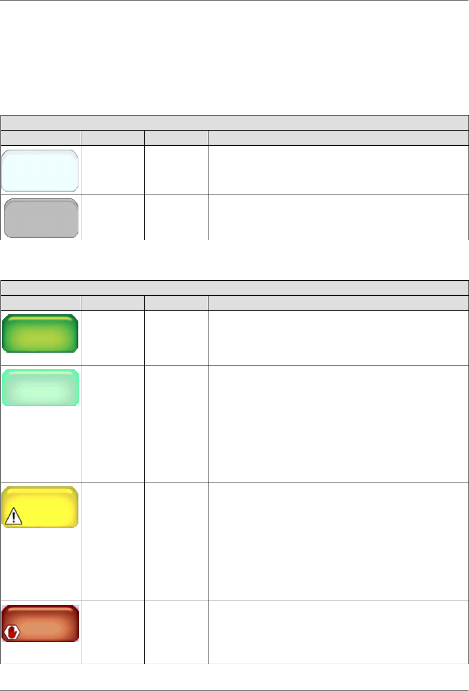
Table 5-1 Zone State Reference
Zone States
Button Color State Notes
Disabled
Zone 1A
White Disabled The zone is available, but disabled.
Zone 1A
Gray Unavailable The system cannot detect the zone.
Table 5-2 Zone Status Reference
Zone Status
Button Color Status Notes
Zon
e 1A
Set
Point
176_C
145_
__
_
C
Zone 1A
145_ C
Dark green Ready/OK The zone is enabled and has reached its set point
temperature.
Zone 1A
145_
__
_C
Zone 1A
145_ C
Light green Waiting for
Ready
The zone is enabled and is in the process of heating to its
set point temperature.
S
The zone is enabled and is in the process of heating to
its set point temperature.
S
The system is in either Standby or Ready Delay mode.
S
A zone or pump is in an alert or fault condition.
S
The system itself is in an alert or fault condition.
Zone 1A
Alert
Yellow Alert The zone is enabled, but the system has detected an alert
condition. Touch the zone with the alert to view system
message.
NOTE: In an alert condition, both the master Heater
and Pump controls remain On.
You have two minutes from the time the system
detects an RTD or an over/under temperature
condition before the alert condition is upgraded to a
fault condition.
Zone 1A
Fault
Red Fault The zone is enabled, but the system has detected a fault
condition. Touch the zone with the alert to view system
message.
NOTE: In a fault condition, both the master Heater
and Pump controls are switched Off.