1.011.1_VPC使用手册.pdf - 第114页
113/144 3. The header view shows all global in formation for the selected inspection. 4. The inspection pattern view shows all the inspection patterns available in the inspection plan, their number, and the num ber of so…
112/144
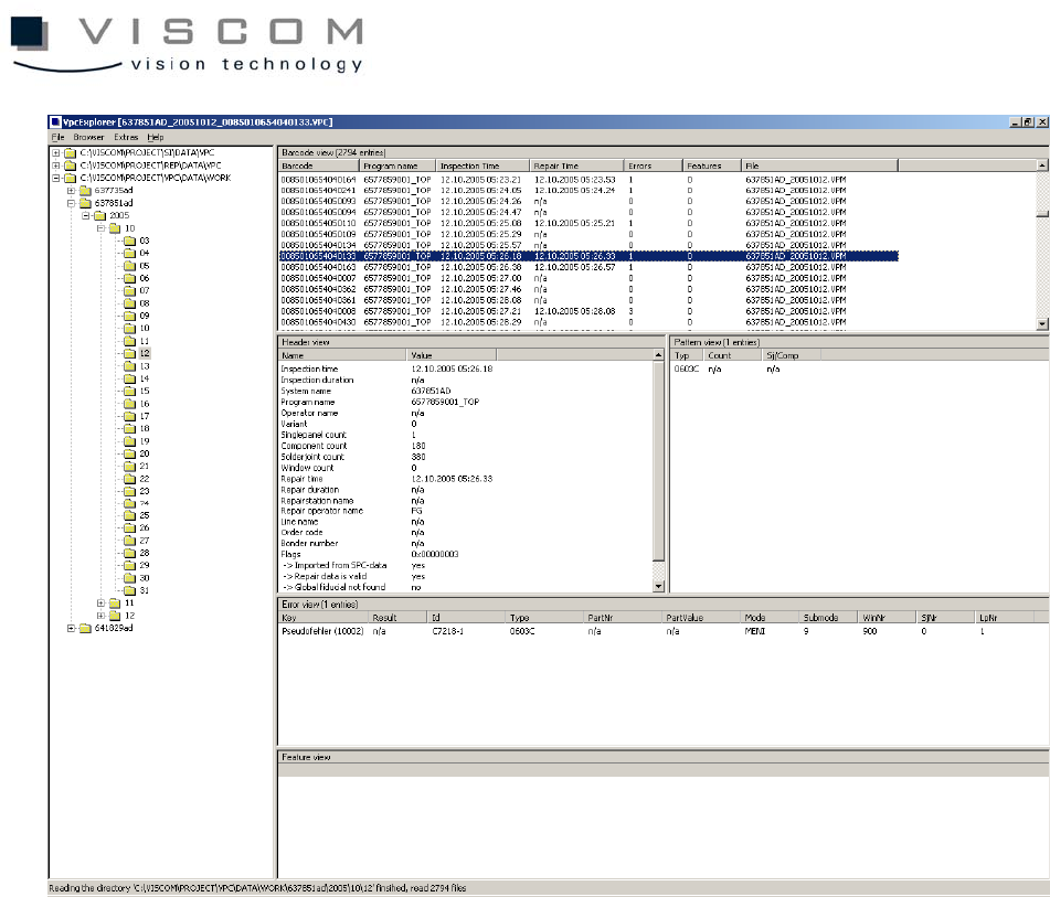
1. The directory view on the left side allows directories to be chosen. By using
the context menu or the menu "Browser", individual root knots can be added.
2. The barcode view is the uppermost area on the right side. Here, the
inspections found in all the directories selected on the left are listed out,
regardless if they are present as VPC or VPM files. Clicking on the column
heading starts a sorting which shows the following information for every
inspection:
• barcode
• inspection plan
• inspection time
• repair time
• number of defect entries
• number of feature entries
• names of the VPC or VPM files that contain barcodes

113/144
3. The header view shows all global information for the selected inspection.
4. The inspection pattern view shows all the inspection patterns available in the
inspection plan, their number, and the number of solder joints. For imported
SPC files, only the inspection pattern names can be shown.
5. The defect view shows all the defects of the selected inspection. The following
fields are shown in detail:
• defect key
• results code
• Id
• inspection pattern
• material number
• component value
• mode und submode
• window and solder joint number
• PCB number
6. The features view shows all the feature values of the selected inspection. All
fields below the fifth are displayed, so defect keys and results codes are
replaced by feature keys and feature values.

114/144
8.3 Setting Up the Defect Definition
Defect definition assigns defect descriptions to the individual defect codes that
are used for all VPC evaluations.
Defect definitions are configured in the file “VpcDefectDefinition.ini“ by default;
the name of this file can also be changed by adapting the corresponding
reference in the individual configurations files.
Currently, the defect definition must be processed manually with a Texteditor;
an interactive processing in the VPC software will be available in the future.
Defect definition is constructed according to the standard of a Windows INI file
and consists of the following sections:
8.3.1 DefectColors
Here, numbers are assigned to colors in the RGB scheme, and the individual
defect definitions are referred to the colors through the numbers. The syntax of
a line is:
<COLORNUMBER> = #<RRGGBB>
• COLORNUMBER is an arbitrary number;
• RRGGBB is assembled from three two-digit hexadecimals corresponding
to the color components.
As an example, the following entries assign the color number "0" to a strong
red:
0=#FF0000
8.3.2 DefectGroups
Here, numbers are assigned to textual defect groups, and the individual defect
definitions are referred to the defect groups by the numbers. The syntax of a
line is: