1.011.1_VPC使用手册.pdf - 第125页
124/144 8.6.7 Generating the VpcDefectDefini tion.ini file The VpcDefectDefinition is generated automatically from the VpcSetup- Program. When this is done, the settings in the si_spc.dcol file are converted as in "…

123/144
Here, the value <RR> stands for the hexadecimal value of red; <GG> for the
hexadecimal value for green, and <BB> for the hexadecimal value for blue.
8.6.5 Si_spc.par file
The si_spc.par file is syntactically analyzed. The entries in si_spc.par are
assigned to their corresponding parameters in Vpc.ini according to the following
form:
[SECTION]
<PARAMETERNAME> = <PARAMETERVALUE>
• [SECTION]: gathers individual parameters into a group.
• PARAMETERNAME: explicit designator to identify a parameter
• PARAMETERVALUE: in most cases, 0 or 1. May also correspond to
another value (such as RGB value, seconds, minutes, counts, etc.).
8.6.6 Si_spc.button file
Entries of the si_spc.button file are also converted to the new convention.
These entries appear in the following form:
<NUMBER> <DIAGRAMDESIGNATOR> <DIAGRAMNAME>
These entries are transferred to the Vpc.ini file, like they were in the section
[Configurations]
<NUMBER> <DIAGRAMDESIGNATOR> <DIAGRAMNAME>
• NUMBER: is continuously assigned
• DIAGRAMDESIGNATOR: explicit designation of the diagram
• DIAGRAMNAME: the name of the diagram designation

124/144
8.6.7 Generating the VpcDefectDefinition.ini file
The VpcDefectDefinition is generated automatically from the VpcSetup-
Program. When this is done, the settings in the si_spc.dcol file are converted as
in "Error definition setup".
125/144
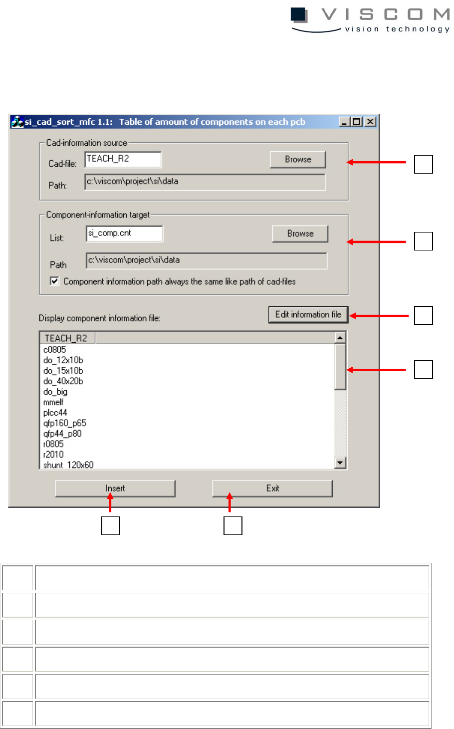
8.6.8 Utility Si_cad_sort_mfc
For more detailed information, see Viscom Online Help.
1 selecting a path to the inspection plan
2 path to the where the list is saved
3 edits the list as notepad
4 component forms in the inspection plan
5 paste
6 cancel
1
2
3
4
6
5