1.011.1_VPC使用手册.pdf - 第28页
27/144 1 2 3 4
26/144
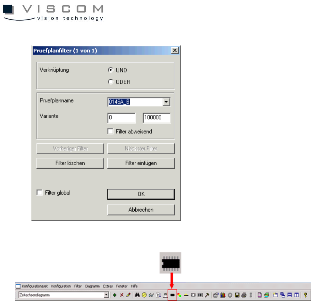
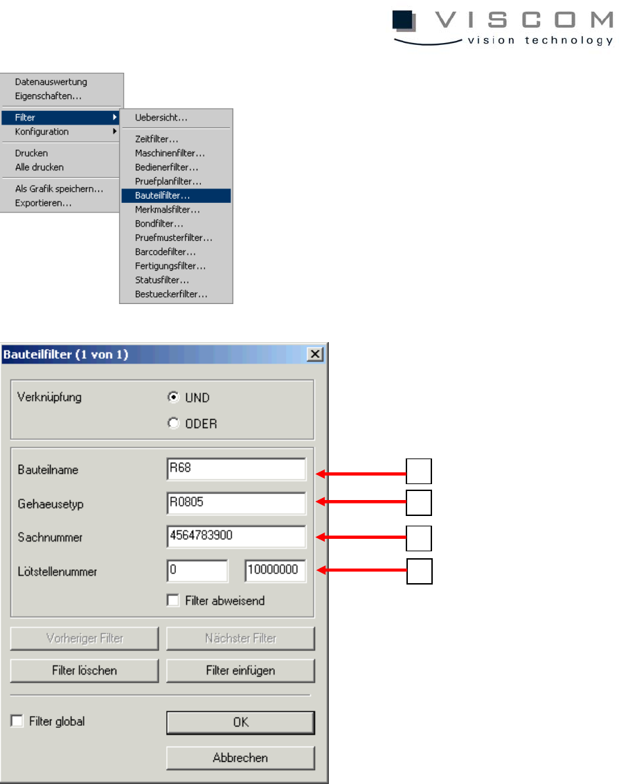
1.6.7 Component filter
The component filter defines the component type (component name or body
type and solder joint number) for which the VPC data should be evaluated. The
entry of wildcards (*) is allowed.
27/144
1
2
3
4
28/144
1 entry of the component name (component ID)
2 entry of the component body type (body type)
3 entry of the article number (6th column Cad file)
4 entry of the solder joint number
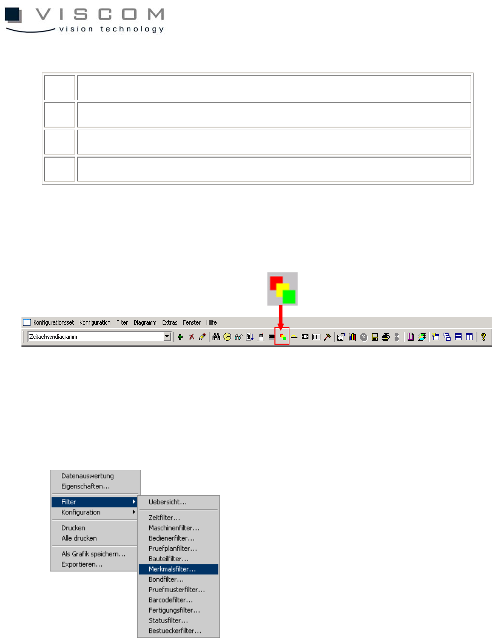
1.6.8 Features filter
The features filter defines the features that should be evaluated in the VPC file.
Features are defined as the defect classifications of defects at the repair station.
The following defect features can be indicated: