1.011.1_VPC使用手册.pdf - 第76页
75/144 1. Defect-free and defective PCBs ar e called up at the repair station and repaired, so there is no good/bad so rting at the AOI and all PCBs are routed to one magazine. For this, parameter 56 P_REP_GOOD in si.par…
74/144
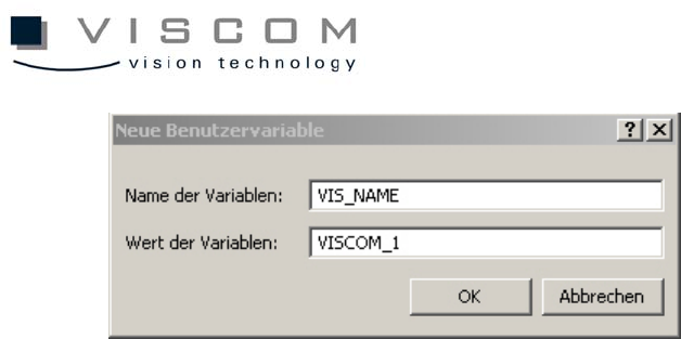
After the variable is defined, the SI software has to be restarted.
4.2.2 Configuration of the si.par
The si.par in the AOI data directory contains the general parameters for
operating the PCB inspection system. It also contains the values of specific
parameters, line by line. The lines have the following format: first, parameter
number; second, parameter value; third, mnemonic abbreviation for the type of
parameter; and fourth, explanatory comment. If the parameter 178
P_SPC_DEST is still present in si.par, it must be either deleted or commented
out. An entry becomes a commentary line when there is * in front of the
corresponding parameter.
There are two different modes for the repair station display; they have basically
no influence on the handling of the VPC files. They are explained here only
briefly.
4.2.3 Configuration of si.tpar
When a central server is used to evaluate the VPC data, the si.tpar file must be
modified at the AOI and the corresponding path must be defined.
TPAR_VPC_PASSED or TPAR_VPC_FAILED are the two entries that define
where the corresponding data should be filed.
Example: TPAR_VPC_PASSED K:\WORK

75/144
1. Defect-free and defective PCBs are called up at the repair station and
repaired, so there is no good/bad sorting at the AOI and all PCBs are
routed to one magazine.
For this, parameter 56 P_REP_GOOD
in si.par is set to 1 and for the general creation of VPC files,
parameter 354 P_VPC_DEST is set to 1.
2. Only defective PCBs are called up at the repair station and repaired; no
.res file is generated for PCBs without defects. So here, the inspected
PCBs are sorted into good and bad at the AOI.
For this, parameter 56 P_REP_GOOD is set to 0
and for the general creation of VPC files,
parameter 354 P_VPC_DEST is set to 1.
Required Directories:
If the repair data should be processed with Rep_server / Rep_client, an
"Outgoing" directory has to be available in the data directory.
4.2.4 Configuration of the si_sj.cnt
The file si_sj.cnt is the reference for determining the number of solder joints. It
contains information about the number of solder joints of the individual
component types (entering wildcards (*) is permitted). This file must be created
and maintained manually. It must be available and identical on all systems.
To activate si_sj.cnt for the VPC evaluation, the file si_sj.cnt.no in the AOI data
directory has to be renamed si_sj.cnt.
If the file si_sj.cnt is not available, a PPM-based evaluation is not possible.
PPM stands for parts per million. It indicates the ratio of real solder joint defects
to the total number of solder joints (equation: defective solder joints / total
number of solder joints * 1,000,000).
76/144
Example: 500 PPM pseudo defects are allowed. This means that out of one
million solder joints, 500 are allowed to be mistakenly indicated as defects by
the machine.
The utility si_cad_sort_mfc can be used to verify which component types are
available (a detailed description of this utility can be found in the appendix). If
there are undefined component types in si_sj.cnt, a warning message appears
when the inspection plan is generated.
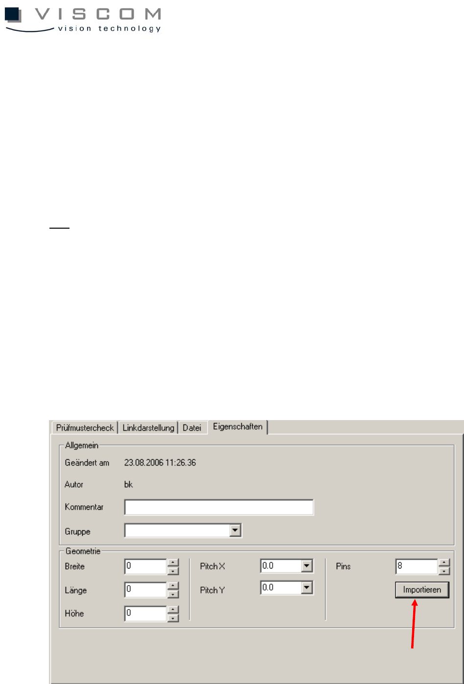
TIP:
With the global library, it is also possible to make a component's solder joints
available directly in the VPC inspection window, and so avoid si_sj.cnt entirely.
The keyword for this is #CLE_PINS, and should be entered in the header of
every CLE file.
Also, the bit 0x20 must be set in parameter 250 P_DATA_GEN_CONF, so that
this entry can be used.
If a si.sj.cnt is already available, it can be used in the inspection pattern editor
and imported separately, which results in the automatic entry #CLE_PINS.