1.011.1_VPC使用手册.pdf - 第78页
77/144
76/144
Example: 500 PPM pseudo defects are allowed. This means that out of one
million solder joints, 500 are allowed to be mistakenly indicated as defects by
the machine.
The utility si_cad_sort_mfc can be used to verify which component types are
available (a detailed description of this utility can be found in the appendix). If
there are undefined component types in si_sj.cnt, a warning message appears
when the inspection plan is generated.
TIP:
With the global library, it is also possible to make a component's solder joints
available directly in the VPC inspection window, and so avoid si_sj.cnt entirely.
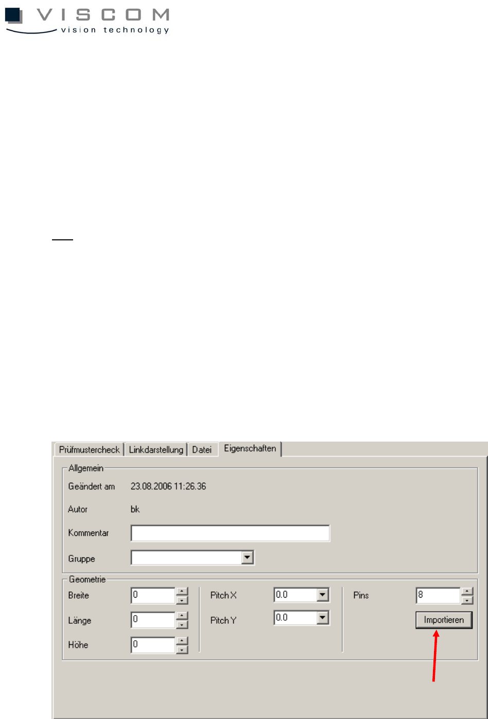
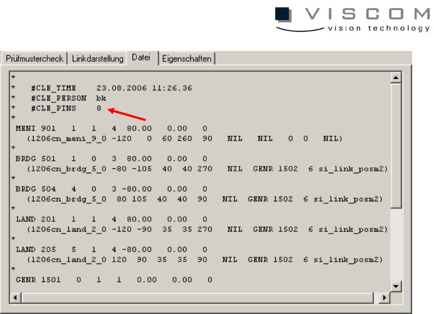
The keyword for this is #CLE_PINS, and should be entered in the header of
every CLE file.
Also, the bit 0x20 must be set in parameter 250 P_DATA_GEN_CONF, so that
this entry can be used.
If a si.sj.cnt is already available, it can be used in the inspection pattern editor
and imported separately, which results in the automatic entry #CLE_PINS.
77/144

78/144
4.2.5 Connecting the repair station
The repair station has to be mapped under R:\ and have a subdirectory R:\VPC.
That is where the SI software files called "visname_date_barcode.VPC" are
created.
4.2.6 Connecting the VPC Server
The VPC Server has to be mapped under S: and have a subdirectory
S:\WORK.