1.011.1_VPC使用手册.pdf - 第73页
72/144 4.1 Standard Configuration 4.1.1 VPC D ata Fl ow (Cla ssica l Var iant) Inspection sys tem VPC Serv er VPC files for bad PCBs Repa ir st ation VPC files for repaired PCBs VPC files for good PCBs
71/144
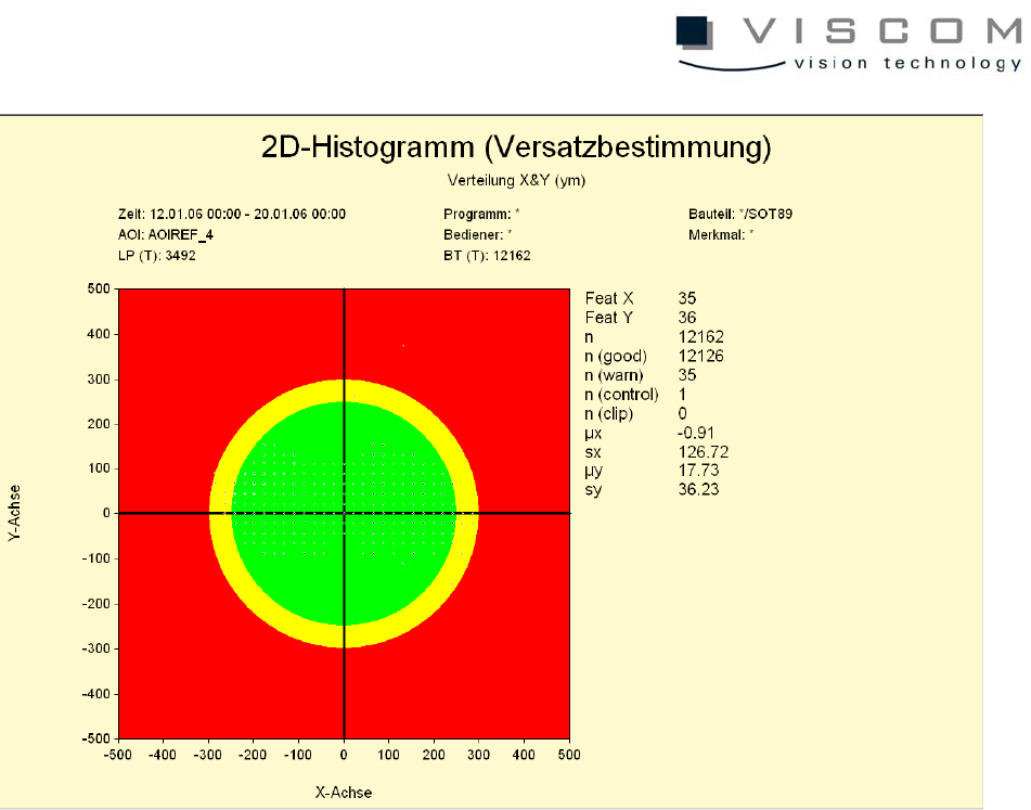
The data evaluation shows an axis cross histogram with colored limits, in which
the displacement is indicated by points with different sizes. The larger a point is,
the more measurement values form the basis of the point. As in the one-
dimensional histogram, additional measurement values that result from the
diagram are also displayed here.
4. Data Flow between the Individual Components and its
Configuration
Before the VPC server is ready to work with, the AOI and the repair station have
to be configured. For this, there are four different modes of data flow between
the components AOI, repair station and VPC server.
72/144
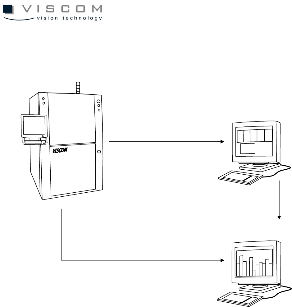
4.1 Standard Configuration
4.1.1 VPC Data Flow (Classical Variant)
Inspection system
VPC Server
VPC files for bad PCBs
Repair station
VPC files for repaired PCBs
VPC files for good PCBs
73/144
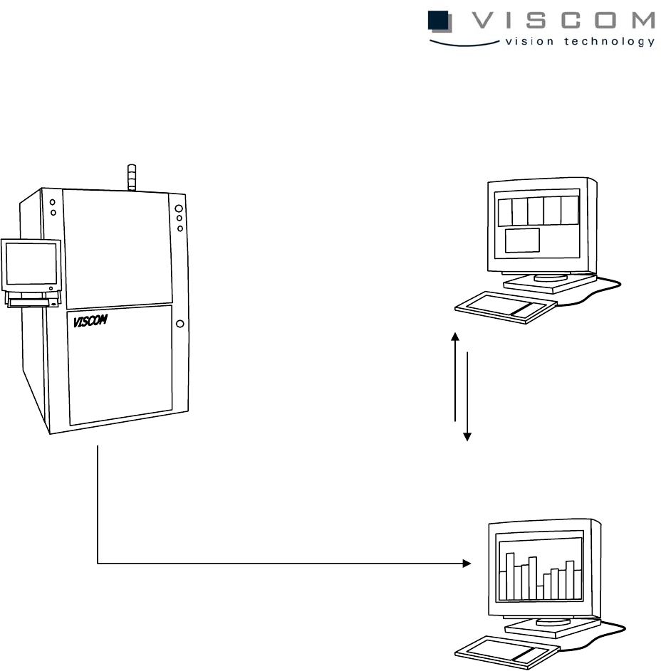
4.1.2 Data Flow VPC (Server)
4.2 Configuration of the AOI
The following steps have to be done to configure the AOI:
4.2.1 Defining the machine name
First, the machine name must be defined in "System Properties". The "System
Properties" window is called up through the start menu ("Settings" - "Control
panel" - "System"). In the submenu "Environment", an environment variable
"VIS_NAME must be defined with the machine name, such as VISCOM 1. The
machine name may not have any empty spaces. Confirm the entry with the
button "Set" and close the window with "OK". If the environment variable
VIS_NAME is not defined, the default machine name is NO_NAME.
Inspection system
VPC Server
Repair station
1. Repair station accesses
VPC files for bad PCBs
VPC files for good and bad PCBs
2. VPC files are re-written
on the SPC server after
PCB repair