00197042-04_SM_X-Serie-S_Customer_EN.pdf - 第105页
4 Electrics and control system 4.2 BoxPC Service Manual SIPLACE X-Serie S 06/2019 105 4.2.1.1 Replacing the BoxPC 627x/827x Overview Fig.122: Installation point BoxPC (example of SIPLACE X4i S shown) Installation Locati…
4 Electrics and control system
4.2 BoxPC
104 Service Manual SIPLACE X-Serie S 06/2019
4.2 BoxPC
4.2.1 Replacing the Control Computer BoxPC
Parts, equipment and tools
Machine type PC type
SIPLACE
X‑SeriesS
Up to serial no. Gxxxx Control computer BoxPC 827C [03094732-xx]
From serial no. Hxxxx Control computer BoxPC 427D [03114177-xx]
Option for 3D coplan BoxPC ABP402-A CPU1020E 2xPCI SSD (iBase)
[03120423‑xx] (replaces: BoxPC 627C [03094731‑xx])
CAUTION
Additional hardware for the BoxPC
The BoxPC is supplied without the following parts. If required, these must be removed from
the old BoxPC and fitted in the new one or ordered as new parts:
SIPLACE X-Series S up to
Gxxxx,
SIPLACE SX4/DX4
SIPLACE X-Series S from Hxxxx
(BoxPC 427D)
Hotlink interface For BoxPC 827C only:
PCI-A24-K01 (1x, with sta-
tionary camera 2x)
[03052135-xx]
Cable: hotlink interface/
power [03042074-xx]
4.2.8 "Replacing the Hotlink
interface card" [}111]
No hotlink interface
GigE interface
(cameras)
No GigE interface GigE ethernet adapter PCI-E I340-T4
[03105575‑xx]
CAN card BoxPC 827C only:
CAN card COM168V2-PCI
[03079973‑xx] (replaces:
[03052590‑xx])
In machines from Hxxxx, this task is assumed
by the "CAN Interface CINX" [03108598‑xx].
This is connected to the BoxPC427D
[03114177‑xx] via a LAN cable (see also 4.9
"Replacing the CAN interface CINX (from
serial no. Hxxxx)" [}126]).
RAM
See 4.2.9 "Replacing the RAM in the BoxPC" [}112]
Ethernet adapter Permanently installed. Permanently installed.
If a 3D Coplan or a barcode scanner is in-
stalled, the "LAN card PCI Express 2x Gigabit
LAN" [03118416-xx] is needed in addition.
●
Installation Manual Windows Embedded Standard 7 [00197737‑xx]
Removal/installation of coplanarity computer
To replace the coplanarity computer, read the applicable assembly instructions.
●
Assembly instructions "SIPLACE X‑Series S 3D-Sensor Coplanarity" [DEEN:00197395‑xx]
Removal/installation of control computer
► Replace the BoxPC.
4.2.1.2 "Replacing the BoxPC 427x" [}107]
4.2.1.1 "Replacing the BoxPC 627x/827x" [}105]
4 Electrics and control system
4.2 BoxPC
Service Manual SIPLACE X-Serie S 06/2019 105
4.2.1.1 Replacing the BoxPC 627x/827x
Overview
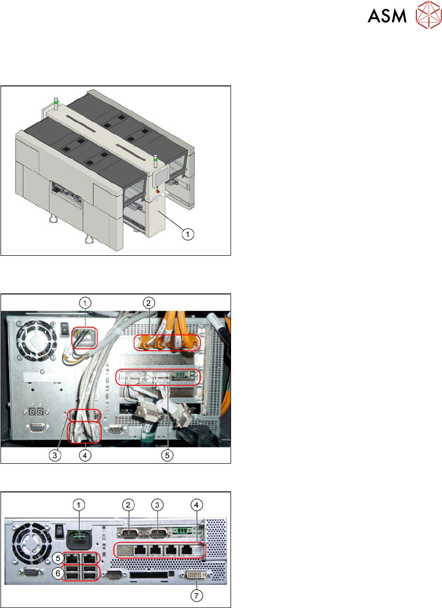
Fig.122: Installation point BoxPC (example of SIPLACE X4i
S shown)
Installation Location
The BoxPC is located behind the cover,
between locations 1 and 2(1).
Fig.123: BoxPC (example of BoxPC 827C)
BoxPC 827C (SIPLACE SX4/DX4,
X‑SeriesS up to no. Gxxxx)
1. Power supply
2. Hotlink interface
Depending on the placement heads
used, there are either one or two hot-
link interfaces fitted.
One hotlink interface: if only C&P20
heads are fitted.
Two hotlink interfaces: all other place-
ment head configurations
3. LAN connections
4. USB connectors
5. CAN card
Fig.124: BoxPC (example of BoxPC 627B)
BoxPC 627C (SIPLACE SX1/SX2/DX1/
DX2, 3D-coplanarity)
1. Power supply DC 24V
2. CAN 1
3. CAN 2
4. Hotlink card
5. LAN connections
6. USB connectors
7. DVI/VGA monitor connection
4 Electrics and control system
4.2 BoxPC
106 Service Manual SIPLACE X-Serie S 06/2019
Removal
► Back up the machine data.
► Switch off the machine, disconnect it from the power supply and secure it to prevent
unauthorized reactivation.
1.2 "Preparatory work..." [}16]
► Unplug all press-fit connections to the BoxPC. If necessary, mark their positions to make clear
assignment easier later on.
►
SIPLACE X-Series S up to no. Gxxxx:
The BoxPC is fixed in the machine with Velcro. Release the BoxPC from the Velcro and
remove it from the machine.
►
SIPLACE X-Series S from No. Hxxxx:
Loosen the screws fastening the Box PC and remove the BoxPC from the machine.
Installation
► Follow the removal instructions in reverse order for installation. Also observe the following
instructions:
●
If parts are missing in the new BoxPC (e.g. ethernet adapter, memory extension), take these
from the old BoxPC and use them in the new one.
4.2.5 "Replacing the CAN card (BoxPC 627B/827C only, up to no. Gxxxx)" [}109]
4.2.6 "Replacing the GigE Ethernet Adapter" [}109]
4.2.7 "Replacing the LAN card (from serial no. Hxxxx)" [}110]
4.2.8 "Replacing the Hotlink interface card" [}111]
4.2.9 "Replacing the RAM in the BoxPC" [}112]
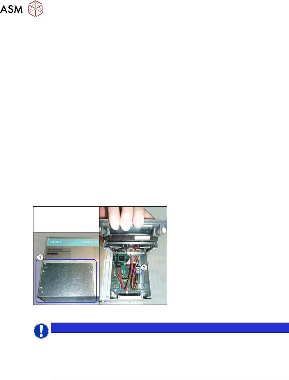
Fig.125: BoxPC (example of 827B)
Hotlink interface power cable
► The hotlink interface power cable
[03042074-xx] (2) needs to be taken
from the old BoxPC and fitted in the
new one. To gain access to this cable,
loosen and open the cover (1) on the
hard drive.
NOTICE
Installing the BoxPC
► The BoxPC needs to be installed after it has been fitted. Read the relevant installation
guide.
► BIOS update and setting images are no longer included on the station software CD.
The CDs for the BIOS settings are only available via the SIPLACE Software Download
Center (SDC).