00197042-04_SM_X-Serie-S_Customer_EN.pdf - 第183页
6 Gantries 6.5 GCU and MGCU Service Manual SIPLACE X-Serie S 06/2019 183 6.5 GCU and MGCU 6.5.1 Replacing the GCU NOTICE MGCU or GCU GCUs and MGCUs are not compatible. A GCU must always be replaced by a GCU and an MGCU m…
6 Gantries
6.4 Trailing cable and printed circuit boards
182 Service Manual SIPLACE X-Serie S 06/2019
DIP switch S1
The DIP S1 switch settings depend on the board version:
DIP switch S1 [03115454-01]
ON OFF Comments
1 ON Spread OFF/ON
2 See text X-Series S: ON
All other machines: OFF
3 See text X-Series S: OFF
All other machines: ON
4 OFF CAN-R ON/OFF
DIP switch S1 [03115454-02 und -03]
ON OFF Comments
1 See text X-Series S: OFF
All other machines: ON
2 OFF Reserved
3 ON EEPROM
4 OFF CAN-R ON/OFF
Removal/installation
► Removal and installation of the VHI is the same as that for the Vision board spread spectrum.
Please read section 6.4.7 "Replacing the Vision board spread spectrum HCU" [}178]. Pay at-
tention to the DIP switch S1.
Troubleshooting
Errors: Image transmission errors occur at cameras of type GigE.
Potential error message:
FM 33332: image transmission to SIPLACE Vision computer interrupted.
Solution: ► Check the DIP switches for the VHI. Pay attention to the function state of the
board.
Errors: When starting the station software, cameras of type GigE are sometimes not re-
cognized.
Potential error messages:
FM 33378: unable to address camera (242).
FM 33209: unable to initialize camera with specified sensor ID.
FM 31904: unable to initialize machine hardware.
Solution: ► Contact the SIPLACE Service team for details.
6 Gantries
6.5 GCU and MGCU
Service Manual SIPLACE X-Serie S 06/2019 183
6.5 GCU and MGCU
6.5.1 Replacing the GCU
NOTICE
MGCU or GCU
GCUs and MGCUs are not compatible. A GCU must always be replaced by a GCU and an
MGCU must be replaced by an MGCU.
Only MGCUs will be fitted from serial number Hxxxx. Please read section 6.5.4 "Replacing
the MGCU" [}186].
Parts, equipment and tools
●
Positioning control unit for gantry axes GCU [03052200-xx]
Overview
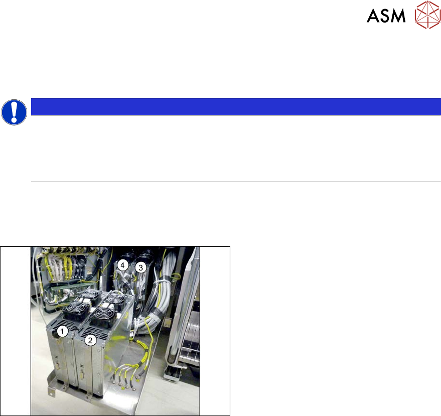
Fig.232: Overview of GCUs
1) to 4) GCUs
The GCUs are located in a rack unit
between locations 1 and 2.
The assignment of GCUs to gantries differs
according to the machine type. Observe the
instructions in section 6.5.3 "Overview of
GCUs" [}185].
Removal
► Switch off the machine, disconnect it from the power supply and secure it to prevent
unauthorized reactivation.
1.2 "Preparatory work..." [}16]
► Unplug all cables from the GCU. If necessary, mark their positions to make clear assignment
easier later on.
► Remove the screws fastening the mount and then remove the mount.
► Remove the GCU from the machine.
Installation
► Follow the removal instructions in reverse order for installation. Also observe the following
instructions:
– Use the DIP switch to set the gantry ID on the GCU.
6.5.3 "Overview of GCUs" [}185]
– Check the firmware and perform a download, if needed.
6.9 "eSW Download (SW 70x)" [}202]
6 Gantries
6.5 GCU and MGCU
184 Service Manual SIPLACE X-Serie S 06/2019
6.5.2 Replacing the GCU fan
Parts, equipment and tools
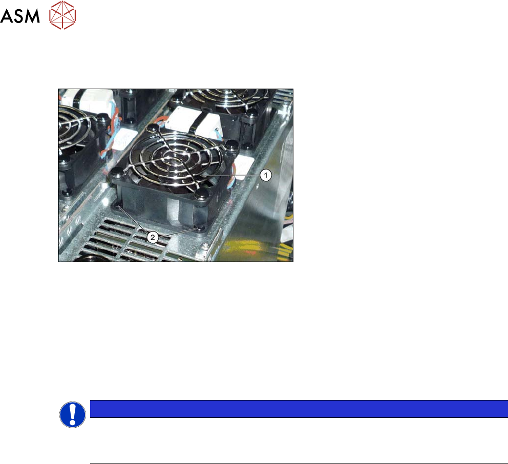
Fig.233: Overview – fan on the GCU
1. GCU fan [03060954-xx]
2. Plastic expansion rivets
(snap rivet DRM 4x4.5-5.5 sw
SR-4070B [03106012-xx])
These are supplied with the fan.
Removal
► Switch off the machine, disconnect it from the power supply and secure it to prevent
unauthorized reactivation.
1.2 "Preparatory work..." [}16]
► Unplug the cable from the fan. You may want to mark the position, to make clear assignment
easier later on.
► Pull out the four expansion rivets on the fan and then remove the fan.
NOTICE
Two-part expansion rivets
The expansion rivets are in two parts.
► First remove the center pin. The lower part can now be easily pulled out.
Installation
► Follow the removal instructions in reverse order for installation. Also observe the following
instructions:
– The expansion rivets are in two parts. First insert the lower part into the hole and then fix
this into place with the upper part.