00197042-04_SM_X-Serie-S_Customer_EN.pdf - 第204页
6 Gantries 6.9 eSW Download (SW 70x) 204 Service Manual SIPLACE X-Serie S 06/2019
6 Gantries
6.9 eSW Download (SW 70x)
Service Manual SIPLACE X-Serie S 06/2019 203
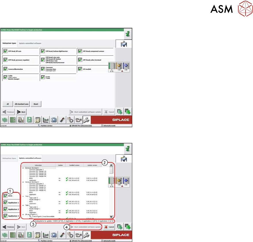
Fig.259: Select subsystem
► Select the subsystem for the eSW
download.
► Click on the Continue button.
Fig.260: Update machine menu
1. Selection buttons:
BIOS
Application 1
Application 2
Application 3
2. Shows the status of the individual sub-
systems
3. Update information
This shows you the number of subsys-
tems which still need to be down-
loaded.
4. Starts the download

6 Gantries
6.9 eSW Download (SW 70x)
204 Service Manual SIPLACE X-Serie S 06/2019
7 Conveyor
Service Manual SIPLACE X-Serie S 06/2019 205
7 Conveyor
DANGER
Observe User Manual
► Please observe the safety instructions in the user manual for all work!
CAUTION
Do not loosen or remove the wrong screws
The following applies to all work performed on the conveyor:
► Make sure that you do not loosen or remove any other screws except those ones ex-
plicitly mentioned. Loosening or removing other screws could lead to irreparable mis-
alignment or damage to the conveyor side.
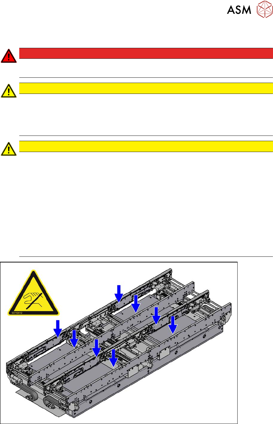
CAUTION
Moving the conveyor sides
The conveyor sides are highly sensitive and should therefore if possible be moved without
releasing the brakes.
Irreparable damage could otherwise be caused to the conveyor sides.
For this reason, try the following options in the order listed:
► We recommend that you use the software to help you move the conveyor sides.
► If this is not possible, the conveyor sides of the dual conveyors can also be moved by
manually docking in the adjustment units (direct switching of valves for the width ad-
justment). Make sure that the cylinders engage in all clamping units of a particular
conveyor side. The conveyor sides can then be moved by carefully pulling the toothed
belt of the width adjustment unit.
► If this is not possible either, the brakes of the dual conveyors can manually be re-
leased using a pin. Take special care not to distort the conveyor sides.
Fig.261: Sensitive conveyor side
See also
2 7.2 "Loosening the Conveyor Side Clamps" [}207]