00197042-04_SM_X-Serie-S_Customer_EN.pdf - 第318页
8 Head exchange 8.6 Replacing the SIPLACE CPP/M 318 Service Manual SIPLACE X-Serie S 06/2019 Fig.406: Cables (up to Gxxxx, without GigE) Up to Gxxxx, without GigE: ► Remove the screws fastening the strain relief (2) on …
8 Head exchange
8.6 Replacing the SIPLACE CPP/M
Service Manual SIPLACE X-Serie S 06/2019 317
Removal
NOTICE
Vacuum test
► If required, perform a vacuum test before removing the placement head.
Read the "Service manual Vacuum test at C&P placement head" [DE+EN:
00196101‑xx] for this.
NOTICE
Fast Hardware Exchange (FHE)
► Observe the instructions in section 8.1 "Fast Hardware Exchange" [}305] when ex-
changing a head.
► Switch off the machine, disconnect it from the power supply and secure it to prevent
unauthorized reactivation.
1.2 "Preparatory work..." [}16]
► Switch off the compressed air supply
5.2 "Disabling the compressed air supply" [}134]
CAUTION
Take great care when dismantling the placement head!
The component sensor prisms, underneath the placement head, could be damaged.
► Never place the placement head down on the component sensor.
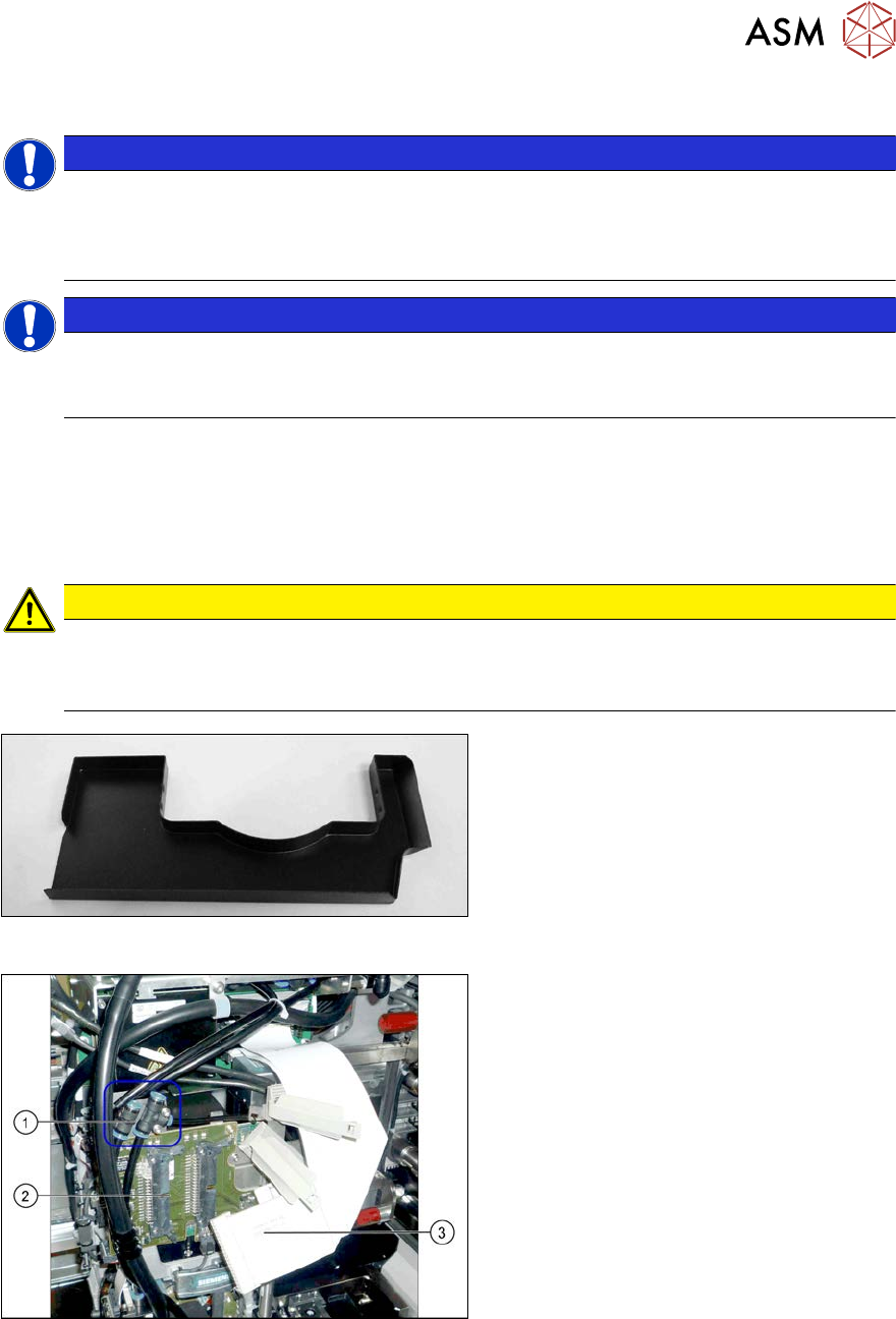
Fig.404: Component sensor protective cap
► Fit the protective cap onto the compo-
nent sensor for the placement head.
Fig.405: Connections
► Unplug the pneumatic connections(1)
from the placement head. You may
want to mark the positions to make
clear assignment easier later on.
► Disconnect the flat ribbon cables(3)
from the intermediate distributor(2).
8 Head exchange
8.6 Replacing the SIPLACE CPP/M
318 Service Manual SIPLACE X-Serie S 06/2019
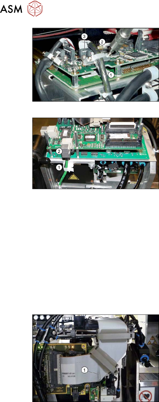
Fig.406: Cables (up to Gxxxx, without GigE)
Up to Gxxxx, without GigE:
► Remove the screws fastening the strain
relief (2) on the component camera cable
(1) and carefully unplug the cable. While
unplugging the cable press the clamps
on both sides of the connector(3). You
may want to mark the positions to make
clear assignment easier later on.
Fig.407: Cables (from Hxxxx, with GigE)
From Hxxxx, with GigE:
► Open the cable holder(1) and unplug the
component camera cable(2).
► Remove all four screws fastening the head with a long Torx screwdriver.
► Carefully lift the head out of the locating pins on the head plate and off the hook.
► Placing the head into the head transport box
Installation
► Follow the removal instructions in reverse order for installation. Also observe the following
instructions:
– If you replace the head without the component camera, you will need to fit the old camera onto
the new head. Read the service manual for your placement head for more information.
– Observe the correct installation height of the head (top or bottom position, see 8.6.1 "Pre-
paring the SIPLACE CPP for the installation height" [}319])!
– Make sure that the assembly position on the head plate is correct.
– Tighten the four fastening screws with a torque of 2.7Nm.
– Make sure that the flat ribbon cable is run correctly to the head adapter (see below).
Fig.408: Flat ribbon cable
Correct running of flat ribbon cable to head
adapter
► Make sure that the flat ribbon cable is run
correctly to the head adapter. In particu-
lar, the cables must lie inside one an-
other at the 90 degrees turn(1) and not
on top of one another, otherwise the con-
nections on the head adapter could be
easily confused.
See also
2 8.8 "Installation Positions on the Head Plate" [}323]
8 Head exchange
8.6 Replacing the SIPLACE CPP/M
Service Manual SIPLACE X-Serie S 06/2019 319
8.6.1 Preparing the SIPLACE CPP for the installation height
CAUTION
Different heights
The placement head can be installed at two different heights. CPP_L corresponds to a
component height of sixmm. CPP_H corresponds to a component height of 11.5mm.
If the SIPLACE CPP is used in a placement area with stationary camera, SIPLACE Twin or
SIPLACE WPC, it may only be used in the upper position!
Overview
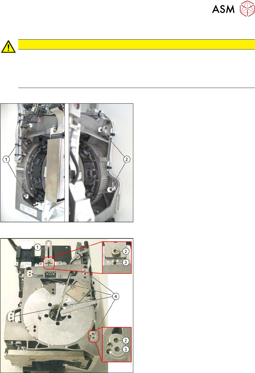
Fig.409: Fastening screws
1. Fastening screws on the left side
2. Fastening screws on the right side
This diagram shows the fastening screws in
the "head at top" position.
Fig.410: SIPLACE CPP – positions
1. Retaining plate
2. "Head at bottom" position
3. "Head at top" position
4. Fixture holes with bushings