00197042-04_SM_X-Serie-S_Customer_EN.pdf - 第358页
9 Component feeding 9.2 COT insert 358 Service Manual SIPLACE X-Serie S 06/2019 9.2.4 Replacing the Feeder Control Unit (FCU) Parts, equipment and tools Fig.480: X-FCU V3, X-Series [03170613S01] ● X-FCU V3, X-Series [03…
9 Component feeding
9.2 COT insert
Service Manual SIPLACE X-Serie S 06/2019 357
► Disconnect the COT insert from all electrical and pneumatic connections. Mark the positions
of these connections, to make clear assignment easier later on. The connection cables and
hoses are located behind the COT insert – in the space leading to the machine base (under
the nozzle changer).
► Dismantle the lower side covers on both sides of the location, so that you can lift the COT in-
sert out later on.
5.5 "Dismantling the Lower Side Cover" [}135]
1
1
3
2
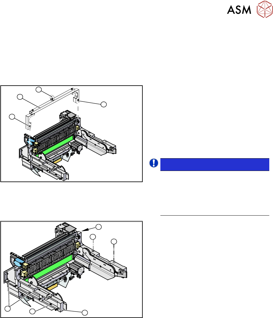
Fig.478: Mounting tool
1. Fixtures
2. Mounting tool
3. Eyelet
► Attach the mounting tool (2) to the fix-
tures provided (1) on the COT insert.
► Fix the lifting device to the eyelet (3) of
the mounting tool (2).
NOTICE!
The COT insert can be installed at dif-
ferent positions in the machine loca-
tion. Mark the position of your COT in-
sert, to ensure that this is sub-
sequently returned to its original posi-
tion.
.
1
1
1
1
2
1
Fig.479: Fastening screws
► Remove the eight fastening screws(1)
of the COT insert.
► Lift the complete COT insert out of the
machine and place it on a suitable sur-
face (four wooden blocks etc.).
► Make sure that you do not damage any
valves, connection cables, hoses etc.
Installation
► Attach the mounting tool to the new COT insert and lift it into the machine, with the help of the
lifting device.
► Reconnect all cables. If required, use the detailed circuit diagrams to help you.
► Move the COT insert into its final position (to the previously marked installation position).
Take care not to damage the cables and hoses.
► Further installation is performed by following the above instructions in the reverse order.
9 Component feeding
9.2 COT insert
358 Service Manual SIPLACE X-Serie S 06/2019
9.2.4 Replacing the Feeder Control Unit (FCU)
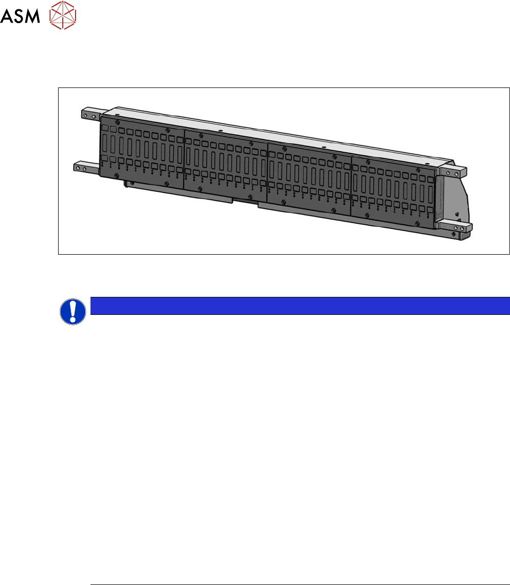
Parts, equipment and tools
Fig.480: X-FCU V3, X-Series [03170613S01]
●
X-FCU V3, X-Series [03170613S01] (replaces: [03096377‑xx], [03059623Sxx])
NOTICE
Observing the technical information
Observe the technical information "Replacing the FCU" (SIPLACE X-Series, SX4/DX4,
X‑SeriesS, Docking Station) [DE: TI2014-11D15] [EN: TI2014-11E15]:
Since June 2010, the "nozzle changer control" and the "cutter control" have been integrated
into the "X-FCU / SIPLACE X-Series" [03059623-xx]. The CAN nodes are therefore no
longer used.
The assembly is, however, not 100% downwards compatible with regard to the mechanical
installation.
There is a spare parts kits available for the SIPLACE X-Series [03059623Sxx] which en-
ables you to convert from [03020068‑xx] to [03059623‑xx]. However, this spare parts kit
does not contain any parts (additional cables) needed for conversion of the docking station
[00116933‑xx].
► COT insert SIPLACE X-Series
In the X-Series, the FCU X-Series [03020068-xx] has been replaced with a new X-
FCU / SIPLACE X‑Series [03059623‑xx]. This new X-FCU has been fitted in the
SIPLACE X-Series with the insert [03066685‑xx] since July 2010.
If you need to fit an X-FCU as a spare part in a SIPLACE X-Series with insert
[03015680‑xx] (version 2 or1), you will need to perform the following tasks.
For this purpose, there is a conversion kit available: "Service assembly X-
FCU" [03061715‑xx] which is contained in the spare parts kit for the new "X-FCU
SIPLACE X-Series" [03059623Sxx].
9 Component feeding
9.2 COT insert
Service Manual SIPLACE X-Serie S 06/2019 359
Overview
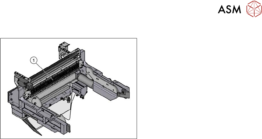
Fig.481: FCU on COTi
1. Feeder control unit (FCU)
The FCU is installed at the locations in the
component trolley feed device.
Removal
► Switch off the machine, disconnect it from the power supply and secure it to prevent
unauthorized reactivation.
1.2 "Preparatory work..." [}16]
► Dismantle the feeder unlocking rail.
► Remove the screws fastening the FCU. Depending on the version, there will be four or six
screws.
► Dismantle the cover plate over the cables.
► Label all cables and the positions of the connectors plugged into the terminal strip of the FCU.
► Unplug all electrical connections from the terminal strip of the FCU.
► Carefully lever the FCU out of the locating pins.
► Remove the earth terminal.
Installation
► Set the DIP switches on the FCU (see 9.2.4.1 "Feeder Control Unit (FCU)" [}360]).
► Place the connection cable in the recess and carefully push in the new FCU. Make sure that
you do not squash any cables.
► Pull the ends of the cables out from under the terminal strip.
► Plug in all electrical connections as labeled on the terminal strip.
► Refit the cover plate and the FCU.
► Further installation is performed by following the above instructions in the reverse order.