00197042-04_SM_X-Serie-S_Customer_EN.pdf - 第362页
9 Component feeding 9.2 COT insert 362 Service Manual SIPLACE X-Serie S 06/2019 9.2.5 Replacing the 40-fold feeder unlock device CAUTION Feeder unlock device on the manual table Replacement of the feeder unlock device on…

9 Component feeding
9.2 COT insert
Service Manual SIPLACE X-Serie S 06/2019 361
LED (test mode for reject box switched off – S2.1 ON) [03059783-04]
LED Color Status Signal name Description
H1, H2, H3, H4 GN Sequential shift
light
LED1, 2, 3, 4 FCU OK
H1, H2, H3, H4 GN ON LED1, 2, 3, 4 eSW application missing
H1, H2, H3, H4 GN Flashing LED1, 2, 3, 4 FCU error, reboot place-
ment machine or replace
FCU
LED (test mode for reject box switched on – S2.1 OFF) [03059783-04]
LED Color Status Signal name Description
H1 or H2 or H3
or H4
GN Flashes LED1 or 2 or 3
or 4
No sensor connected for
reject box 1 or 2 or 3 or 4
H1 or H2 or H3
or H4
GN OFF LED1 or 2 or 3
or 4
Sensor for reject boxes 1
or 2 or 3 or 4 connected
and no reject box inserted
H1 or H2 or H3
or H4
GN ON LED1 or 2 or 3
or 4
Sensor for reject boxes 1
or 2 or 3 or 4 connected
and no reject box inserted
Button S1 [03059783-04]
Button Status Function Description
S1 OFF RESET When pressed
DIP switch S2 [03059783-04]
Switch Status Signal name Description
S2.1 ON/OFF FCU_ENV3 ON: test mode for reject box switched off
OFF: test mode for reject box switched on
S2.2 OFF FCU_ENV2 40-fold FCU
S2.3 ON/OFF FCU_ENV1 ON: without insert control, with virtual but-
ton
OFF: with insert control, without virtual but-
ton
S2.4 ON/OFF FCU_ENV0 ON: with tape cutter and with nozzle
changer functionality
OFF: without tape cutter and without nozzle
changer functionality
If an "X-FCU / X-Series" [03059623-xx] is fitted as replacement for an "FCU X-Series" [03020068-
xx] in the "COT insert X-Series" or at the "Docking station for component trolley SIPLACE X", you
need to set the DIP switch as follows:
Switch Status Comment
S2.1 ON Test mode for reject bin switched off
S2.2 OFF FCU for 40 feed tracks
S2.3 OFF COT insert control with pushbutton / without button GUI (vir-
tual).
S2.4 OFF "HW version 6" meaning without tape cutter and nozzle
changer functionality
9 Component feeding
9.2 COT insert
362 Service Manual SIPLACE X-Serie S 06/2019
9.2.5 Replacing the 40-fold feeder unlock device
CAUTION
Feeder unlock device on the manual table
Replacement of the feeder unlock device on the manual table is the same as that for the
COT insert. However, you need to first dismantle the front and back sections for the manual
table.
This section describes replacement using the example of the COT insert.
Parts, equipment and tools
●
Feeder unlock device 40-fold [03011582-XX]
Overview
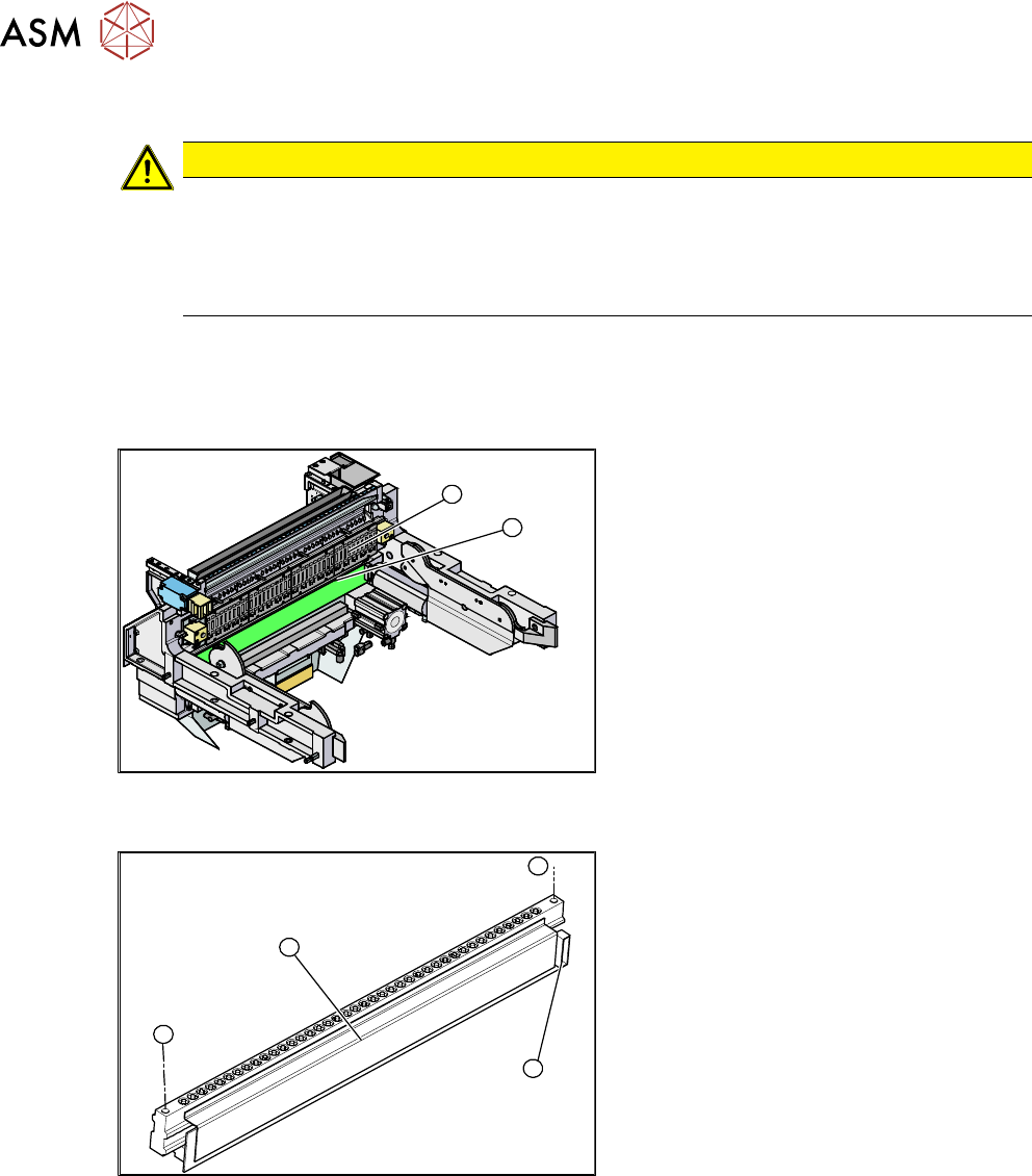
2
1
Fig.484: Feeder unlock device and FCU (example of
SIPLACE X‑Series shown)
1. Feeder unlock device (under the FCU)
2. Feeder control unit (FCU)
The feeder unlock device is installed at the
locations in the COT insert.
1
1
3
2
Fig.485: Feeder unlock device (example of SIPLACE
X‑Series shown)
1. Two fastening screws
2. Complete feeder unlock device
3. Connector for flat ribbon cable
Removal
► Switch off the machine, disconnect it from the power supply and secure it to prevent
unauthorized reactivation.
1.2 "Preparatory work..." [}16]
► Unplug the flat ribbon cable from the connector.
► Remove the two fastening screws.
► Pull the flat ribbon cable out of the side of the connector. You may have to lift the feeder un-
lock device slightly to do this.
► Lift the feeder unlock device up and off and unplug the pneumatic connection.
9 Component feeding
9.2 COT insert
Service Manual SIPLACE X-Serie S 06/2019 363
Installation
► Reconnect the system to the electrical and compressed air systems.
NOTICE
Pneumatic connection
You might find it advisable to loosen the cover on the back of the COT insert. This gives the
compressed air hose more room to be moved. In certain circumstances, the COT insert
may need to be loosened and pulled out slightly to the front.
► Carefully press the feeder unlock device towards the back and insert the fastening screws.
CAUTION
Do not pinch the cable
Make sure not to pinch or damage the cables running at the back (connected to the FCU).
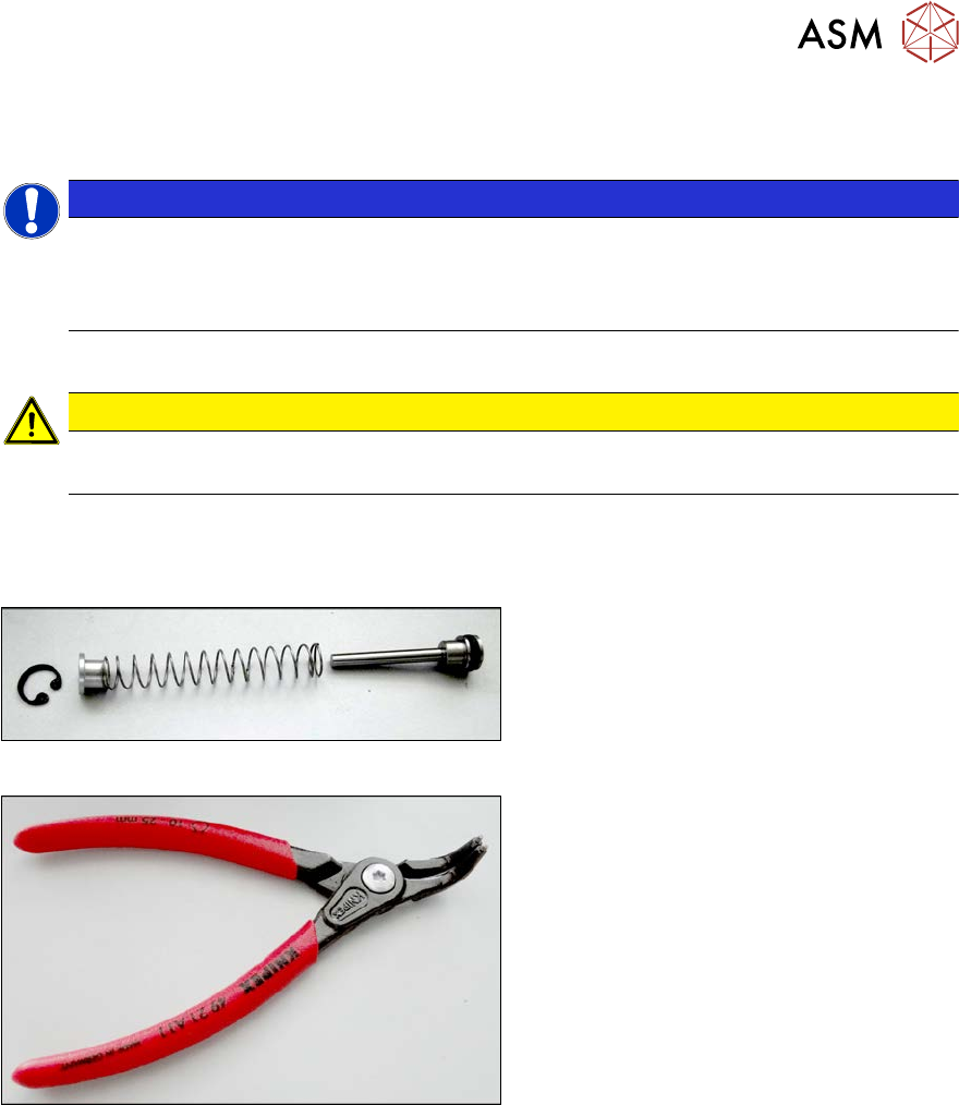
9.2.6 Replacing the unlocking pins
Parts, equipment and tools
Fig.486: ETP feeder unlock device
●
SPP feeder unlock device [03088220-xx]
Fig.487: Inside circlip pliers, bent tips J01
●
Inside circlip pliers, bent tips J01
[00365186‑xx]
●
Snipe nose pliers [00353833-xx]