00197042-04_SM_X-Serie-S_Customer_EN.pdf - 第217页
7 Conveyor 7.3 Lifting Table Service Manual SIPLACE X-Serie S 06/2019 217 7.3.5 Setting the Parallelism and Height of the Lifting Table Plate DANGER Press the EMERGENCY STOP! Before performing adjustment work you must en…
7 Conveyor
7.3 Lifting Table
216 Service Manual SIPLACE X-Serie S 06/2019
7.3.4 Calibrating the lifting table motor
After completing the work on the lifting table, this will need to be calibrated.
Procedure
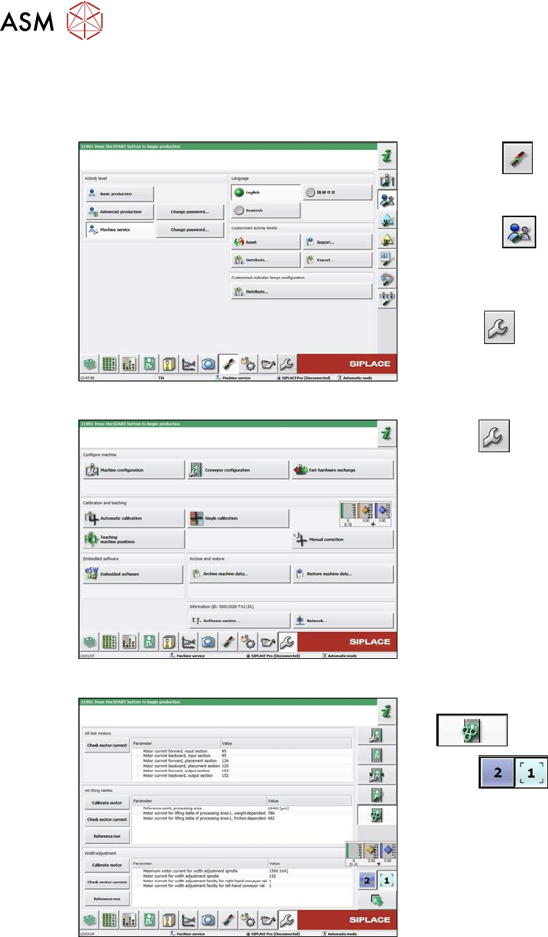
Fig.275: Select operator level
► Select the
button, to open the
Configure, update and calibrate the
machine menu.
► Select the
button to open the
Check and set user settings menu.
► Switch over to the operator level Ma-
chine service.
ð The
button will be shown.
Fig.276: Service menu
► Select
.
► Select Conveyor configuration.
Fig.277: Conveyor ( ??) menu
► Select Initiate conveyor parameters
.
► Select
to choose the re-
quired conveyor lane.
► In the relevant section, select the Cali-
brate motor button.
► Check the clamps (distance between clamping plate and clamping rail) and adjust if neces-
sary.
7.3.5 "Setting the Parallelism and Height of the Lifting Table Plate" [}217]
7 Conveyor
7.3 Lifting Table
Service Manual SIPLACE X-Serie S 06/2019 217
7.3.5 Setting the Parallelism and Height of the Lifting Table Plate
DANGER
Press the EMERGENCY STOP!
Before performing adjustment work you must ensure that the lifting table has been secured
against movement!
Overview
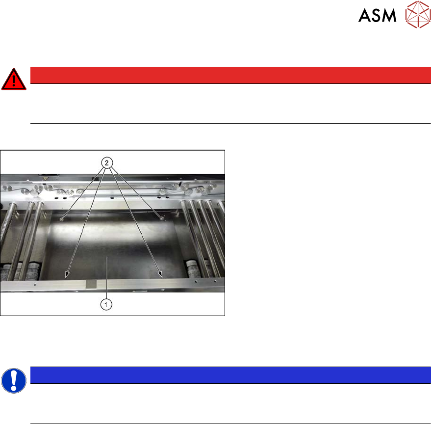
Fig.278: Lifting table plate
1. Lifting table plate
2. Fastening screws for lifting table plate
Setting
NOTICE
Single, dual conveyor
The setting is shown in the diagram using the example of a lifting table unit for the dual con-
veyor (DC). Setting the single conveyor (SC) follows the same procedure.
► Use the software to move the conveyor sides to maximum width.
7.2 "Loosening the Conveyor Side Clamps" [}207]
► Remove the screws fastening the lifting table plate (countersunk screws) but do not remove
the lifting table plate.
► Use the software to clamp the lifting table (without board).
► Underneath the fastening screws, there are setting screws (Allen key5).
Use these setting screws to set the lifting table plate so that it has no play between it and the
clamping edge.
► Check all four corners of the lifting table for any play.
► Check the setting by clamping a board into place. Check all corners to see whether there is
any play.
► Insert and tighten the four screws fastening the lifting table plate.
► Calibrate the zero position of the lifting table motor.
7 Conveyor
7.4 Conveyor Drive
218 Service Manual SIPLACE X-Serie S 06/2019
7.4 Conveyor Drive
7.4.1 Replacing the conveyor drive
Parts, equipment and tools
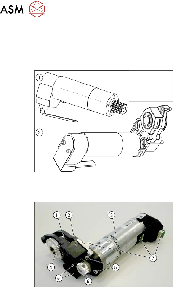
Fig.279: Spare parts for conveyor drive
●
(1) DC drive motor with synchronizing
disk SXa [03093387‑xx]
or
(2) Drive unit assembly SXa
[03092345‑xx] (incl. drive bracket,
toothed belt, etc.)
●
Bearing for hexagonal shaft SXa
(plastic bearing) – pack of 10
[03092024-xx]
●
Sealing varnish Loctite 241 [02101037-
xx]
Overview
Fig.280: Overview of conveyor drive
1. Toothed belt on conveyor drive
2. Drive bracket
3. Motor
4. Drive shaft
5. Four motor fastening screws on the
drive bracket (torque = 0.7 Nm)
6. Motor shaft
7. Electrical connections (incl. shield con-
nection)