00197042-04_SM_X-Serie-S_Customer_EN.pdf - 第378页
9 Component feeding 9.3 X-Series Component Trolley 378 Service Manual SIPLACE X-Serie S 06/2019 9.3.7 Replacing the Actuator/Protective Bracket Parts, equipment and tools 00376503-xx Set of Torx offset screwdrivers with …
9 Component feeding
9.3 X-Series Component Trolley
Service Manual SIPLACE X-Serie S 06/2019 377
9.3.6 Replacing the insert feeder
Parts, equipment and tools
Select the right insert feeder:
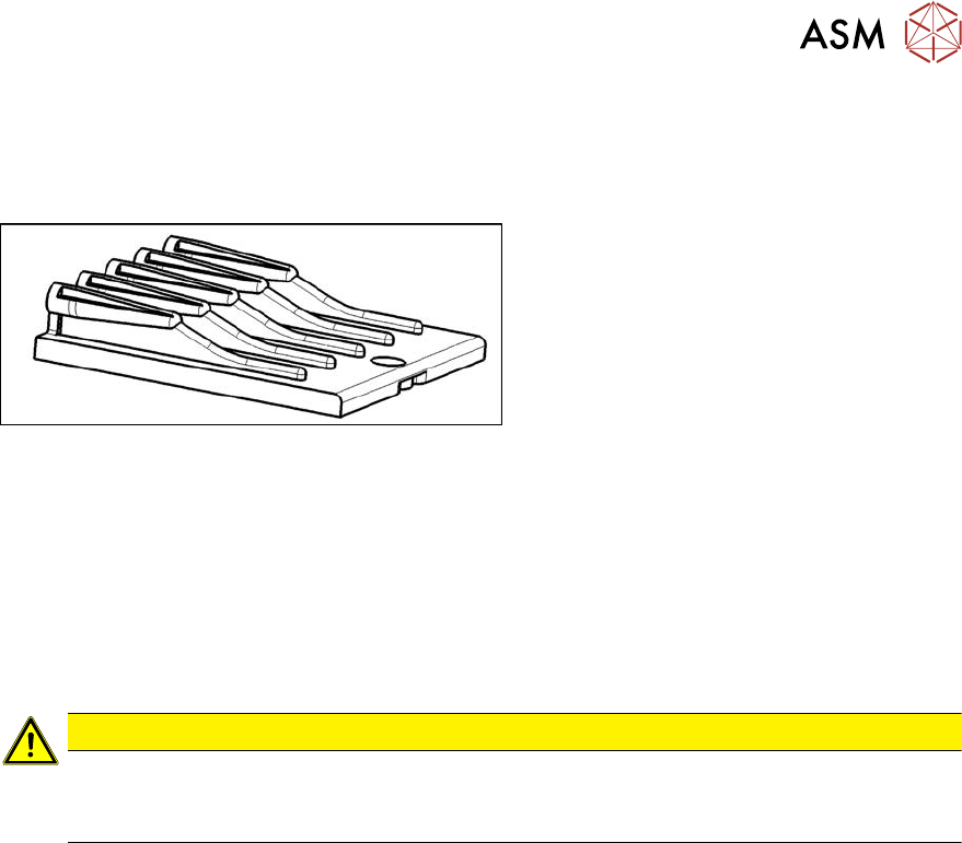
Fig.506: Insert feeder [03002898-xx]
Insert feeder [03002898-xx]
Suitable for:
●
X-Series component trolley
●
Component trolley SX1/SX2 (30 or 60
tracks)
●
Manual table X-Series S
Removal
► Move the component trolley out of the machine.
► Loosen the screw fastening the guide profile and remove the guide profile.
Installation
► Follow the removal instructions in reverse order for installation. Also observe the following
instructions:
CAUTION
Installation instructions
► Make sure that the insert is aligned properly with the guidance behind it. You must be
able to push feeder modules into the feeder location without edge interference.
9 Component feeding
9.3 X-Series Component Trolley
378 Service Manual SIPLACE X-Serie S 06/2019
9.3.7 Replacing the Actuator/Protective Bracket
Parts, equipment and tools
00376503-xx Set of Torx offset screwdrivers with spherical heads
Torx wrench TX20 with drilled hole
00353832-xx Allen key set
00334892‑xx Loctite 243
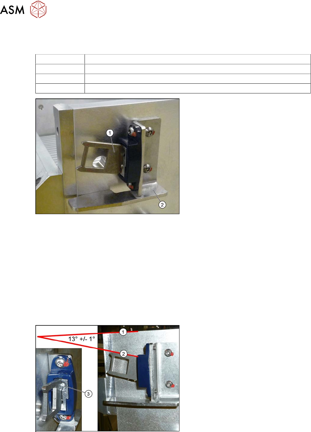
Fig.507: Actuator
1. Actuator AZ335 Schmersal
[03013488‑xx]
2. Protective bracket: holder and protec-
tion for actuator [03095447-xx]
●
Torque wrench TX20 with drilled hole
(for screw ISO 7380-TX with pin - M4)
Removal
► Remove the two screwsfastening the actuator/protective bracket and then remove the actu-
ator/protective bracket.
Installation
► Follow the removal instructions in reverse order for installation. Also observe the following
instructions:
Fix the actuator with two fastening screws to the protective bracket (torque 2.0Nm, Loctite 243).
► Set the actuator as follows:
Setting
Fig.508: Setting the actuator
► Set the actuator with the help of the ad-
justment screw (3).
Between the upper edge(1) of the
table and the actuator(2) you need to
set an angle of 13°+/‑1°.
The actuator must be able to slide into
the safety switch without rubbing
against the plastic.
9 Component feeding
9.4 Docking Station for Component Trolley
Service Manual SIPLACE X-Serie S 06/2019 379
9.4 Docking Station for Component Trolley
DANGER
Observe User Manual
► Please observe the safety instructions in the user manual for all work!
9.4.1 Docking station for component trolley - overview
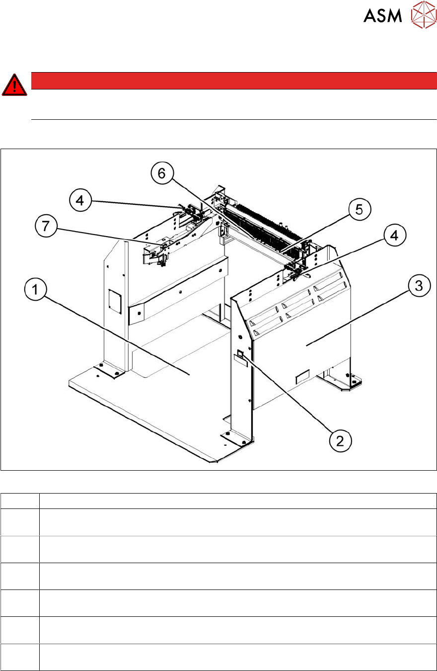
Fig.509: Docking station – front
1 Docking station – assembly [00116933-xx]
2 Unlocking pushbutton [00334095-xx]
9.4.10 "Replacing the unlocking pushbutton" [}392]
3 Power pack and pressure control valve for locking cylinder (behind the cover)
9.4.2 "Replacing the power pack" [}381]
4 Locking lever [03025104-xx]
9.4.5 "Replacing the locking lever" [}384]
5 Feeder unlock device 40-fold [03011582-XX]
9.4.7 "Replacing the 40-fold feeder unlocking device" [}387]
6 Feeder Control Unit (FCU)
9.4.8 "Replacing the Feeder Control Unit (FCU)" [}388]
7 Short-stroke cylinder for locking unit [03034831‑xx]
9.4.4 "Replacing the locking unit short-stroke cylinder" [}383]