00197042-04_SM_X-Serie-S_Customer_EN.pdf - 第373页
9 Component feeding 9.3 X-Series Component Trolley Service Manual SIPLACE X-Serie S 06/2019 373 9.3.3 Replacing the locking latch Parts Fig.499: Locking latch and cover plate 03069205-xx Single locking latch 03077142-xx…
9 Component feeding
9.3 X-Series Component Trolley
372 Service Manual SIPLACE X-Serie S 06/2019
9.3 X-Series Component Trolley
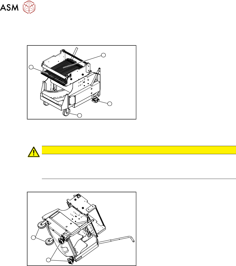
9.3.1 SIPLACE X-series component trolley
1
4
3
2
Fig.497: SIPLACE X-series component trolley
1. Guide castor
2. Fixed castor
3. Locking strip
4. Support block
9.3.2 Replacing the Fixed/Guide Castors [00341918-xx]
CAUTION
Heavy machine part!
The component trolley must be placed on one side in order to remove the fixed/guide
castors. The component changeover table is extremely heavy! You will need two people to
perform this task.
Parts, equipment and tools
1
2
Fig.498: Fixed and guide castors (example of SIPLACE
X‑Series shown)
1. Fixed castor [00341918-xx]
2. Guide castor [03004958-xx]
●
Second person
Removal/Installation
► Remove all feeders from the component trolley.
► Move the component trolley out of the machine.
► Place the component trolley down on its side, on a suitable surface.
► Undo the screws fastening the fixed/guide castor to to replaced and then remove the castor.
► Insert the new fixed/guide castor.
► Stand the component trolley on its wheels again.
9 Component feeding
9.3 X-Series Component Trolley
Service Manual SIPLACE X-Serie S 06/2019 373
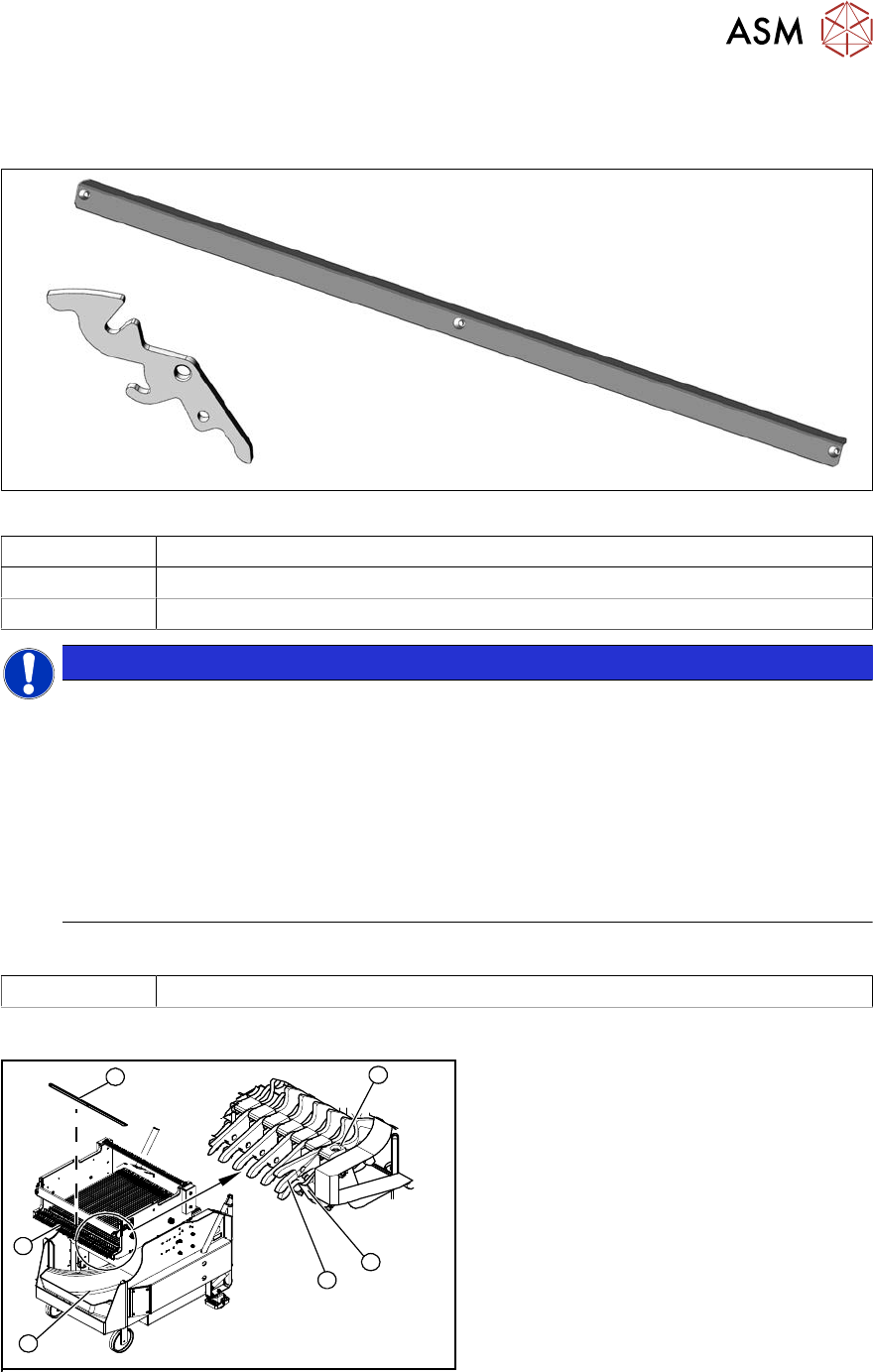
9.3.3 Replacing the locking latch
Parts
Fig.499: Locking latch and cover plate
03069205-xx Single locking latch
03077142-xx Cover plate for locking strip
03010352-xx Tension spring
NOTICE
SIPLACE TX/X/SX-Series component trolley
Component trolleys from the SIPLACE TX, SX and X-Series (S) require a locking latch for
each feeder track.
► Feeder lock [03023777-xx] with 40 locking latches
(1x per component trolley SIPLACE TX/X-Series (S)/SX4)
► Feeder lock [03057284-xx] with 30 locking latches
(1x per 30 track, 2x per 60 track component trolley SIPLACE SX1/SX2)
ð The feeder lock can also be completely dismantled from the component trolley and
replaced.
Equipment and tools
00353832-xx Allen key set
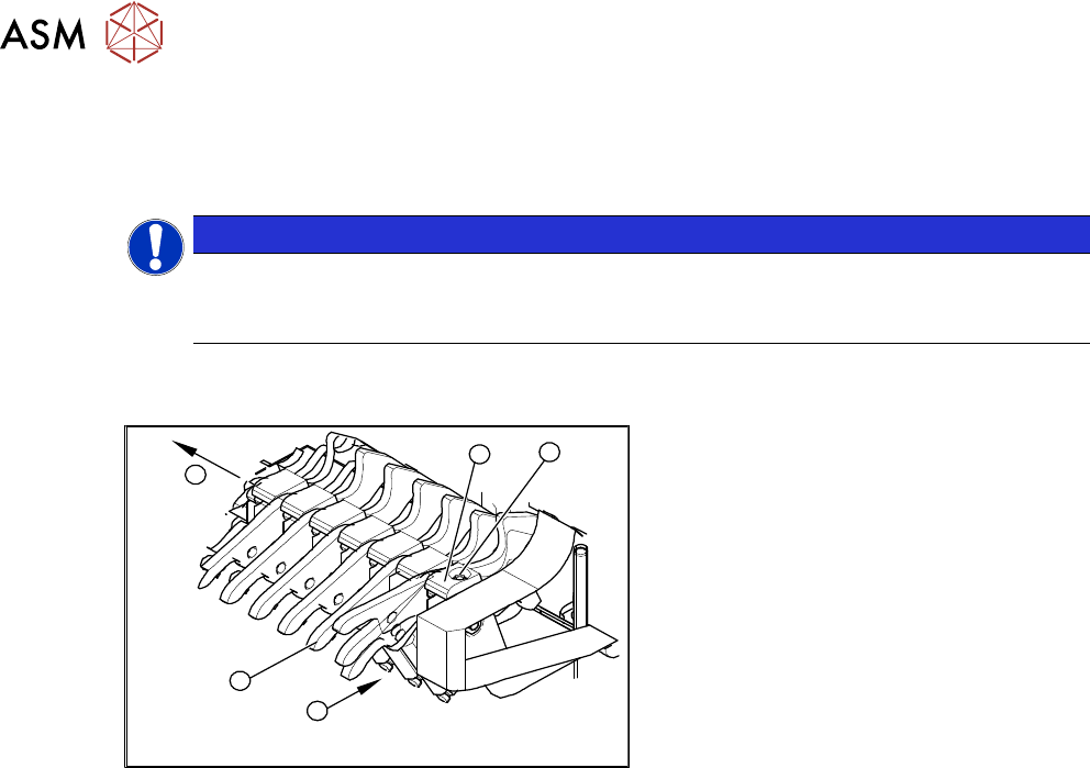
Overview
4
6
5
1
3
2
Fig.500: Locking latch on component trolley
1. Waste tape container
2. Cover
3. Position of complete feeder locking
mechanism
4. Locking latch
5. Tension spring
6. Pressure plate (under cover(2))
9 Component feeding
9.3 X-Series Component Trolley
374 Service Manual SIPLACE X-Serie S 06/2019
Removal and installation
► Remove the waste tape container (1) and empty it.
► Refit the waste tape container. This makes sure that any parts which fall down are not lost.
NOTICE
Waste tape container
You can use the waste tape container as a surface on which to place small parts (tension
springs, locking latches etc.).
► Remove the screws fastening the cover plate locking rail [03077142-xx](2). Use a suitable
Phillips screwdriver to avoid damaging the screws.
4
5
1
3
2
Fig.501: Removing the locking latch
► Unhook all tension springs (1) from the
locking latches (2).
► Remove the screws (3) fastening the
pressure plates(4).
► Pull out the locking latches with the
shaft(5).
► The locking latches can now be pushed
off the shaft.
► Return the locking latches, including
the new one, to the shaft.
► Fit the locking latches and shaft.
► During reassembly, take care to keep the pressure plates in their correct position (4). These
are not symmetrical and will not hold the shaft properly if placed in a certain (incorrect) posi-
tion.
► When tightening the fastening screws (3), make sure that the pressure plates (4) are not at an
incorrect angle and that the locking latches do not jam.
► Hook the tension springs (1) back up.
► Refit the cover.