00197042-04_SM_X-Serie-S_Customer_EN.pdf - 第334页
9 Component feeding 9.1 Cutter 334 Service Manual SIPLACE X-Serie S 06/2019 9.1.5 Replacing the baffle plate Parts Fig.430: Baffle plate 03019896‑xx Baffle plate Equipment and tools 00353832-xx Allen key set Wire cutter…
9 Component feeding
9.1 Cutter
Service Manual SIPLACE X-Serie S 06/2019 333
Removal
NOTICE
Same procedure
The removal and installation is described below using the example of the metal buffer. The
removal and installation of the spacer is the same as that for the metal buffer.
► Switch off the machine, disconnect it from the power supply and secure it to prevent
unauthorized reactivation.
1.2 "Preparatory work..." [}16]
► Remove the cutter from the machine.
9.1.3 "Replacing the Cutter on the COT Insert [03066690-xx]" [}329]
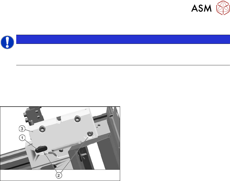
Fig.429: Removing the metal buffer
► Remove the plastic cover(1).
► Take out the screws(2).
► Remove the complete mounting
strip(3).
► Remove the metal buffer.
Installation
► Follow the removal instructions in reverse order for further installation.
9 Component feeding
9.1 Cutter
334 Service Manual SIPLACE X-Serie S 06/2019
9.1.5 Replacing the baffle plate
Parts
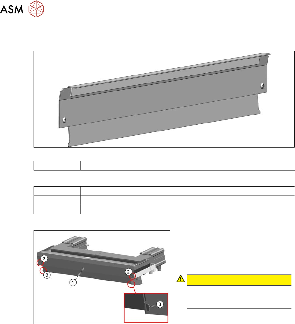
Fig.430: Baffle plate
03019896‑xx Baffle plate
Equipment and tools
00353832-xx Allen key set
Wire cutters
Cable ties
Overview
Fig.431: Cutter
1. Baffle plate [03019896-xx]
2. Two fastening screws
3. Clip connecting baffle plate and pro-
tective plate
CAUTION!
Risk of injury
There is a risk of injuring yourself on
the cutting edge of the blades.
.
Removal
► Switch off the machine, disconnect it from the power supply and secure it to prevent
unauthorized reactivation.
1.2 "Preparatory work..." [}16]
► Remove the cutter from the machine.
9.1.3 "Replacing the Cutter on the COT Insert [03066690-xx]" [}329]
► Straighten the two clips with pliers.
► Remove the two screws fastening the baffle plate.
► Remove the baffle plate unit from the cutter.
Installation
► Follow the removal instructions in reverse order for installation.
9 Component feeding
9.1 Cutter
Service Manual SIPLACE X-Serie S 06/2019 335
9.1.6 Replacing the protective plate
Parts
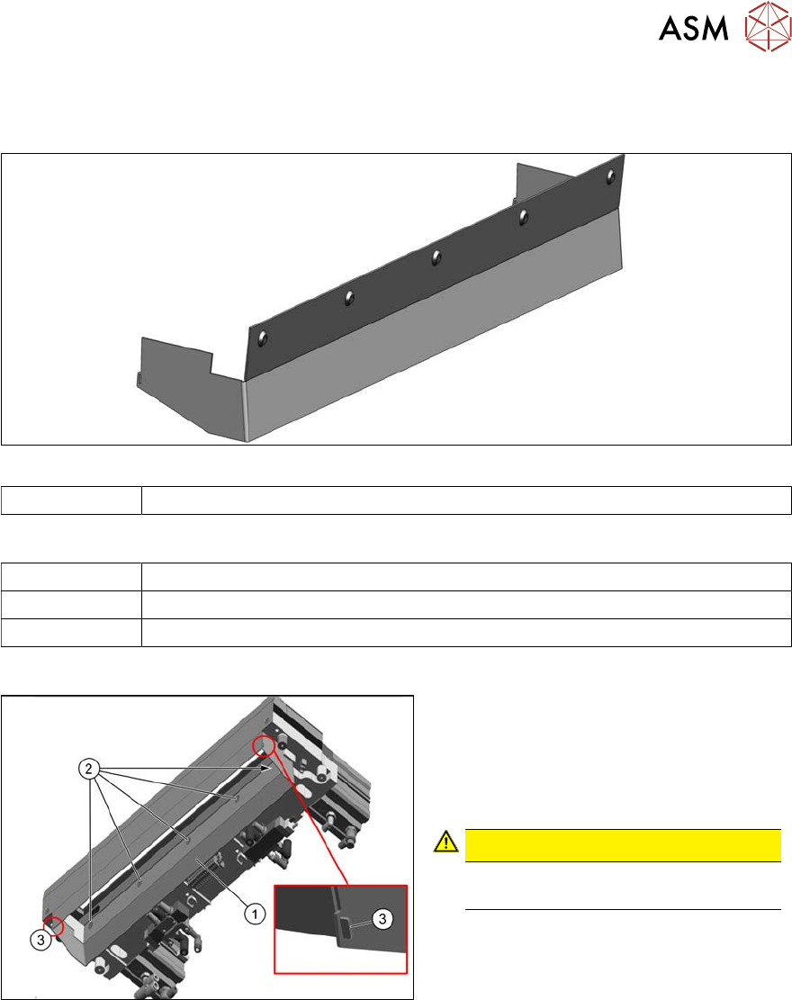
Fig.432: Protective plate
03019894‑xx Protective plate
Equipment and tools
00353832-xx Allen key set
Wire cutters
Cable ties
Overview
Fig.433: Protective plate on cutter
1. Protective plate [03019894-xx]
2. Five fastening screws
3. Clip connecting baffle plate and pro-
tective plate
CAUTION!
There is a risk of injuring yourself on
the cutting edge of the blades.
.
Removal
► Switch off the machine, disconnect it from the power supply and secure it to prevent
unauthorized reactivation.
1.2 "Preparatory work..." [}16]
► Remove the cutter from the machine.
9.1.3 "Replacing the Cutter on the COT Insert [03066690-xx]" [}329]
► Remove the five screws fastening the protective plate.
► Straighten the two clips with pliers.
► Remove the protective plate from the cutter.