00197042-04_SM_X-Serie-S_Customer_EN.pdf - 第328页
9 Component feeding 9.1 Cutter 328 Service Manual SIPLACE X-Serie S 06/2019 9.1.2 Replacing the waste tape slide Parts, equipment and tools ● Used tape chute complete [03067460-xx] ● Allen key set Overview Fig.421: Wast…
9 Component feeding
9.1 Cutter
Service Manual SIPLACE X-Serie S 06/2019 327
9 Component feeding
DANGER
Observe User Manual
► Please observe the safety instructions in the user manual for all work!
9.1 Cutter
DANGER
Observe User Manual
► Please observe the safety instructions in the user manual for all work!
WARNING
Risk of injury when working near the tape cutter.
When working in the area of the tape cutter, move the component trolley out of the machine
and disconnect the machine from the mains supply and the compressed air supply.
► Wait until the operating pressure has dropped to 0 MPa.
► Always secure the machine against unauthorized reactivation.
► Do not reach into the tape cutter.
CAUTION
Risk of injury when performing service work on the tape cutter.
Never support the tape cutter on your body, e.g., on your knees or thighs. Do not place
your feet under the tape cutter.
► Wear appropriately thick protective gloves.
► When removing/fitting the tape cutter, hold it only outside on the left and right.
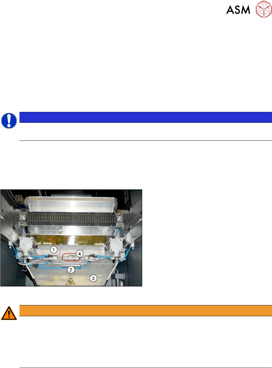
9.1.1 Cutter
Fig.420: Overview of cutter [03066690‑xx]
1. Short stroke cylinder
2. Electrical connection
3. Solenoid valves
9 Component feeding
9.1 Cutter
328 Service Manual SIPLACE X-Serie S 06/2019
9.1.2 Replacing the waste tape slide
Parts, equipment and tools
●
Used tape chute complete [03067460-xx]
●
Allen key set
Overview
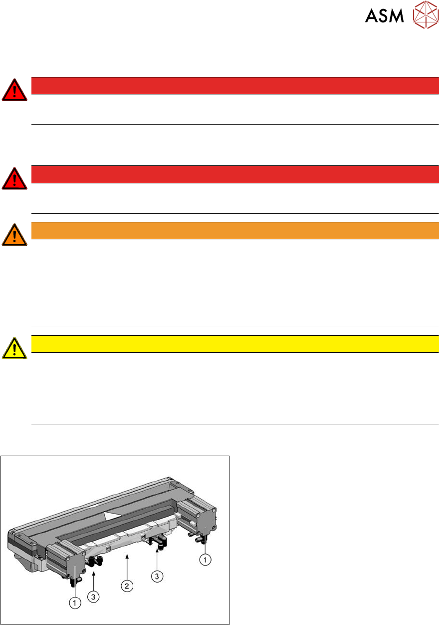
Fig.421: Waste tape slide
1 Waste tape slide 2 COT insert
3 Fastening screw for used tape chute, left 4 Fastening screw for used tape chute,
right
Removal
► Remove the screws fastening the used tape chute.
► Take the used tape chute down and out of the machine.
CAUTION
Risk of cutting
The cutter is located under the tape channel. The blades there have very sharp edges.
► Do not reach into the cutter and make sure that it is never freely accessible.
Installation
► Follow the removal instructions in reverse order for installation.
9 Component feeding
9.1 Cutter
Service Manual SIPLACE X-Serie S 06/2019 329
9.1.3 Replacing the Cutter on the COT Insert [03066690-xx]
Parts, equipment and tools
●
Cutter, pneumatic SIPLACE HF/X-Series [03066690-xx]
●
Screw clamp
●
For additional work to the cutter:
Two large parallel clamps and a sturdy table with even surface, to clamp down the dismantled
cutter
Removal
NOTICE
COT insert
The cutter can be removed without dismantling the COT insert.
► Switch off the machine, disconnect it from the power supply and secure it to prevent
unauthorized reactivation.
1.2 "Preparatory work..." [}16]
► Switch off the compressed air supply
5.2 "Disabling the compressed air supply" [}134]
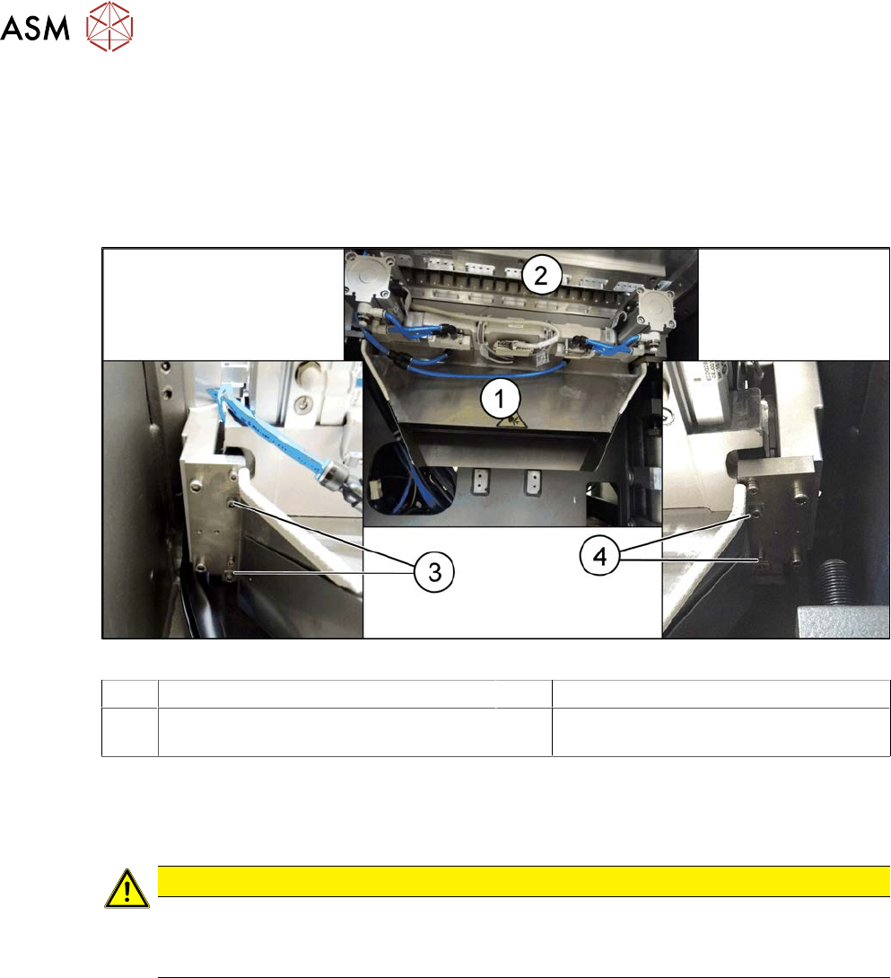
Fig.422: Connectors
► Remove the four screws fastening the
waste tape slide(3) and then remove
the waste tape slide.
► Unplug the compressed air connections
for the short-stroke cylinder (2) at the
coupling.
► Unplug the electrical connections (4)
from the cutter(1) .. To do this, press
the sides of the connector.
WARNING
Risk of injury when releasing the fixtures!
The cutter is only held by the fastening screws and is not supported by other parts. If the
four fastening screws are loosened, the cutter will fall down and out of the machine.
► Make sure that no one is under the cutter.
► Support the cutter by placing a suitable object (e.g. height-adjustable support or chair)
under it.