00197042-04_SM_X-Serie-S_Customer_EN.pdf - 第167页
6 Gantries 6.4 Trailing cable and printed circuit boards Service Manual SIPLACE X-Serie S 06/2019 167 Fig.211: Fastening screws ► Remove the screws fastening the up- per end of the trailing cable. Fig.212: Cables ► Dis…
6 Gantries
6.4 Trailing cable and printed circuit boards
166 Service Manual SIPLACE X-Serie S 06/2019
6.4.1.3 Replacing the Y trailing cable
Parts, equipment and tools
●
Y trailing cable (see above)
●
Hose unlocking tool [03047090-xx]
●
Pipe/hose cutters [00381443-xx]
●
If required, assembly instructions for the "vacuum pump" [00196845‑xx]
●
Sealing varnish Loctite 241 [02101037-xx]
●
Edding marker, white [00382740-xx]
●
Help of second person, if needed
●
Assembly instructions for vacuum pump X series S, SX4/DX4, if required [00196845-xx]
Removal
NOTICE
Vacuum pump
► When a vacuum pump is fitted, also observe the assembly instructions "Vacuum pump
X-Series S, SX4/DX4" [00196845‑xx].
► Switch off the machine, disconnect it from the power supply and secure it to prevent
unauthorized reactivation.
1.2 "Preparatory work..." [}16]
► Switch off the compressed air supply
5.2 "Disabling the compressed air supply" [}134]
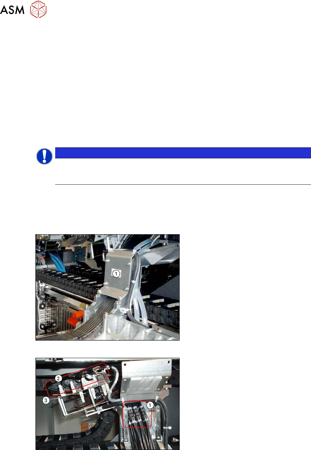
Fig.209: Cover
► Remove the six screws fastening the
cover(1) and remove the cover.
Fig.210: Hoses and connectors
► Mark the positions of the hoses on both
sides of the couplings(1), so that these
can be easily assigned later on.
► Disconnect the the hoses from the
couplings.
► Mark the positions of the connectors(2)
on the gantry interface(3), so that
these can be easily assigned later on.
► Disconnect the cables from the gantry
interface.
6 Gantries
6.4 Trailing cable and printed circuit boards
Service Manual SIPLACE X-Serie S 06/2019 167
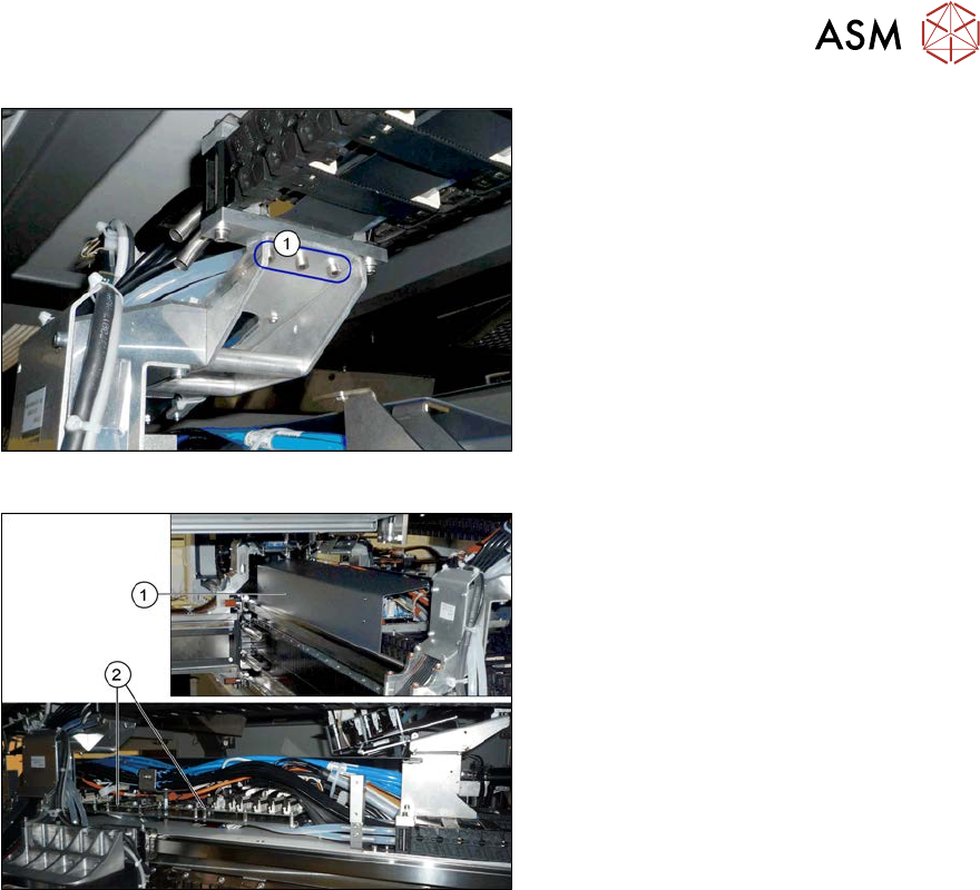
Fig.211: Fastening screws
► Remove the screws fastening the up-
per end of the trailing cable.
Fig.212: Cables
► Dismantle the cover(1) on the trailing
cable interface(2).
► Mark the cables coming from the trail-
ing cable on the trailing cable interface,
to make clear assignment easier later
on.
► Unplug the cables coming from the
trailing cable at the trailing cable inter-
face.
► Carefully remove the trailing cable from the machine. You might need to enlist the help of a
second person.
Installation
► Installation is performed by following the above instructions in the reverse order. Also observe
the following instructions:
– Clean the trailing cable contact surface on the machine base with a dry cloth.
– Always handle the new trailing cable with care.
– Make sure that the flat ribbon cable and the pneumatic hoses are not rubbed against any
parts or folded. Look out for sharp edges.
– Prepare the trailing cable. Place the old and new trailing cables next to one another and
match the length of the new trailing cable hose to the old one.
– For production reasons, the new trailing cable is supplied with a holder. This new holder
can be dismantled before installation and the holder already in the machine can be used
again.
If you use the new holder, you will need to dismantle all attached items (boards etc.) from
the old holder and attach them to the new holder.
– If hose ends were damaged during removal, cut these with hose cutters.
– Carefully insert the new trailing cable into the prescribed position. Make sure you do not
fold or twist the trailing cable.
– Check that the power track chain runs parallel to the machine base. Move the gantry back
and forth.
– If it is difficult to push the hoses onto the tubes, moisten these first with white spirits or iso-
propanol.
– Secure all screws with Loctite 241.
6 Gantries
6.4 Trailing cable and printed circuit boards
168 Service Manual SIPLACE X-Serie S 06/2019
6.4.2 Replacing the Trailing Cable Interface
Parts, equipment and tools
●
Trailing cable interface gantry 2 and 4 assembly [03071356-xx] or
●
Trailing cable interface gantry 1 and 3 assembly [03071355-xx]
NOTICE
Machines from Serial Number Hxxxx
The trailing cable interface version used for machines from serial number Hxxxx must be at
least -02.
Overview
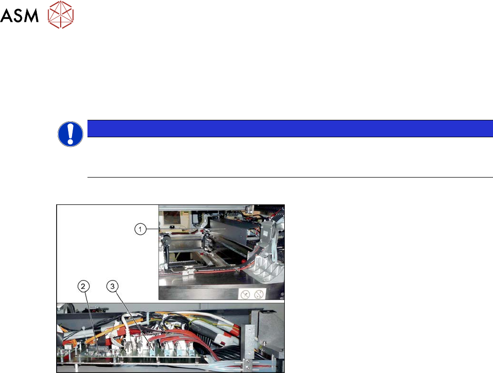
Fig.213: Overview of circuit boards
1. Cover on the trailing cable interface
2. Vision hotlink adapter
3. Trailing unit interface
Removal
► Switch off the machine, disconnect it from the power supply and secure it to prevent
unauthorized reactivation.
1.2 "Preparatory work..." [}16]
► Remove the screws fastening the cover on the trailing cable interface and remove the cover.
► Unplug the electrical connections to the trailing interface. You may want to mark the positions
of these connections to make clear assignment easier later on.
► Remove the screws fastening the trailing interface and remove the interface from the
machine.
Installation
► Follow the removal instructions in reverse order for installation.