00197042-04_SM_X-Serie-S_Customer_EN.pdf - 第359页
9 Component feeding 9.2 COT insert Service Manual SIPLACE X-Serie S 06/2019 359 Overview Fig.481: FCU on COTi 1. Feeder control unit (FCU) The FCU is installed at the locations in the component trolley feed device. Remo…
9 Component feeding
9.2 COT insert
358 Service Manual SIPLACE X-Serie S 06/2019
9.2.4 Replacing the Feeder Control Unit (FCU)
Parts, equipment and tools
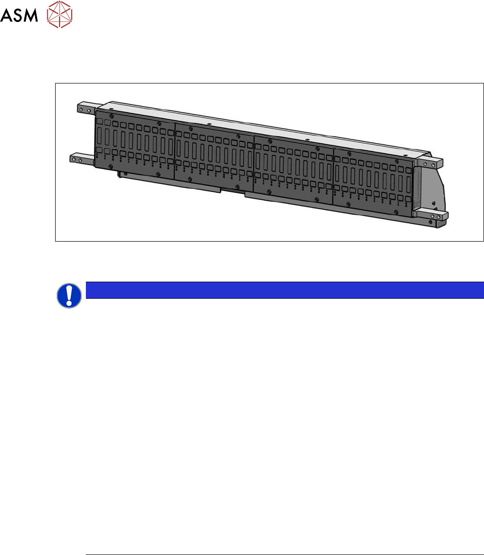
Fig.480: X-FCU V3, X-Series [03170613S01]
●
X-FCU V3, X-Series [03170613S01] (replaces: [03096377‑xx], [03059623Sxx])
NOTICE
Observing the technical information
Observe the technical information "Replacing the FCU" (SIPLACE X-Series, SX4/DX4,
X‑SeriesS, Docking Station) [DE: TI2014-11D15] [EN: TI2014-11E15]:
Since June 2010, the "nozzle changer control" and the "cutter control" have been integrated
into the "X-FCU / SIPLACE X-Series" [03059623-xx]. The CAN nodes are therefore no
longer used.
The assembly is, however, not 100% downwards compatible with regard to the mechanical
installation.
There is a spare parts kits available for the SIPLACE X-Series [03059623Sxx] which en-
ables you to convert from [03020068‑xx] to [03059623‑xx]. However, this spare parts kit
does not contain any parts (additional cables) needed for conversion of the docking station
[00116933‑xx].
► COT insert SIPLACE X-Series
In the X-Series, the FCU X-Series [03020068-xx] has been replaced with a new X-
FCU / SIPLACE X‑Series [03059623‑xx]. This new X-FCU has been fitted in the
SIPLACE X-Series with the insert [03066685‑xx] since July 2010.
If you need to fit an X-FCU as a spare part in a SIPLACE X-Series with insert
[03015680‑xx] (version 2 or1), you will need to perform the following tasks.
For this purpose, there is a conversion kit available: "Service assembly X-
FCU" [03061715‑xx] which is contained in the spare parts kit for the new "X-FCU
SIPLACE X-Series" [03059623Sxx].
9 Component feeding
9.2 COT insert
Service Manual SIPLACE X-Serie S 06/2019 359
Overview
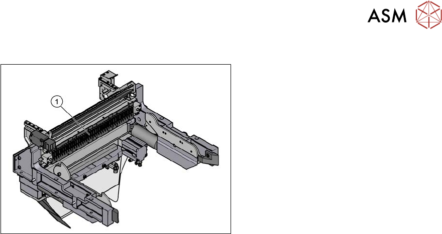
Fig.481: FCU on COTi
1. Feeder control unit (FCU)
The FCU is installed at the locations in the
component trolley feed device.
Removal
► Switch off the machine, disconnect it from the power supply and secure it to prevent
unauthorized reactivation.
1.2 "Preparatory work..." [}16]
► Dismantle the feeder unlocking rail.
► Remove the screws fastening the FCU. Depending on the version, there will be four or six
screws.
► Dismantle the cover plate over the cables.
► Label all cables and the positions of the connectors plugged into the terminal strip of the FCU.
► Unplug all electrical connections from the terminal strip of the FCU.
► Carefully lever the FCU out of the locating pins.
► Remove the earth terminal.
Installation
► Set the DIP switches on the FCU (see 9.2.4.1 "Feeder Control Unit (FCU)" [}360]).
► Place the connection cable in the recess and carefully push in the new FCU. Make sure that
you do not squash any cables.
► Pull the ends of the cables out from under the terminal strip.
► Plug in all electrical connections as labeled on the terminal strip.
► Refit the cover plate and the FCU.
► Further installation is performed by following the above instructions in the reverse order.
9 Component feeding
9.2 COT insert
360 Service Manual SIPLACE X-Serie S 06/2019
9.2.4.1 Feeder Control Unit (FCU)
FCU 80 Mhz (V3)
●
X-FCU V3, X-Series [03170613‑xx]
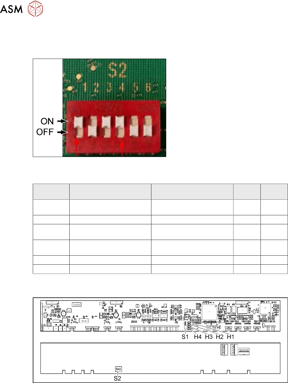
Fig.482: DIP switch S2 (example of FCU 40-fold shown)
► Set the DIP switch according to your
configuration.
DIP switch S2
S2 ON OFF 40 fold
FCU
60 fold
FCU
S2-SW1 Test mode for reject bins dis-
abled
Test mode for reject bins en-
abled
ON ON
S2-SW2 60-fold FCU 40-fold FCU OFF ON
S2-SW3 Without feed control
With virtual button
With feed control
Without virtual button
ON ON
S2-SW4 With tape cutter and NC func-
tion
Without tape cutter and NC
function
ON ON
S2-SW5 Not used Not used OFF ON
S2-SW6 Not used Not used OFF ON
FCU 40 Mhz
●
X-FCU V2, X series [03096377-xx]
Fig.483: FCU board