00197042-04_SM_X-Serie-S_Customer_EN.pdf - 第126页
4 Electrics and control system 4.9 Replacing the CAN interface CINX (from serial no. Hxxxx) 126 Service Manual SIPLACE X-Serie S 06/2019 4.9 Replacing the CAN interface CINX (from serial no. Hxxxx) Parts, equipment and t…
4 Electrics and control system
4.8 Replacing the CAN switch
Service Manual SIPLACE X-Serie S 06/2019 125
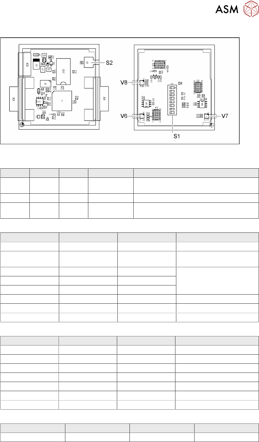
4.8.2 CAN switch
Fig.151: 03083844-02
LED [03083844-02]
LED Color Status Signal name Description
V6 GN/RD ON P20.12/
RST001_N
1 Mbit transmission rate:
GN OK, RD: error
V7 GN/RD ON P20.4/ALE 500 kbit transmission rate: GN OK, RD: error
V8 GN/RD ON P9./CC16IO Transmission rate:
GN 1Mbit, RD 500kbit
Dip switch S1 [03083844-02]
Switch Status Signal name Description
S1.1 OFF P5.0/AN0 ON: DIP test
S1.2 ON/OFF P5.1/AN1 ON: 500 kbit
OFF: 1 Mbit
S1.3 ON/OFF P5.2/AN2 See table Error Frame Limits
S1.4 ON/OFF P5.3/AN3
S1.5 ON/OFF P5.4/AN4
S1.6 OFF P5.5/AN5 OFF: no test, ON: testing
S1.7 ON CAN1RB 120ohms, CAN1
S1.8 ON CAN2RB 120ohms, CAN2
DIP switch S1.3 - S1.5 error frame limits [03083844-02]
S1.3 S1.4 S1.5 Function
OFF OFF OFF 1 error frame
ON OFF OFF 5 error frames/min
OFF ON OFF 10 error frames/min
ON ON OFF 10 error frames/h
OFF OFF ON 50 error frames/h
ON OFF ON 100 error frames/h
OFF ON ON 500 error frames/h
Button S2 [03083844-02]
Buttons Status Signal name Description
S2 When pressed SWITCH_TACT Reset error frame
4 Electrics and control system
4.9 Replacing the CAN interface CINX (from serial no. Hxxxx)
126 Service Manual SIPLACE X-Serie S 06/2019
4.9 Replacing the CAN interface CINX (from serial no. Hxxxx)
Parts, equipment and tools
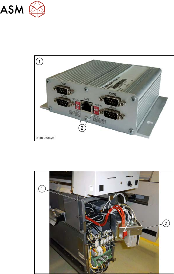
Fig.152: CAN interface CINX
1. CAN Interface CINX [03108598-xx]
2. DIP switches
Overview
Fig.153: CAN interface in the machine
The CAN interface(1) is located between
location 1 and 2, behind the BoxPC(2).
The CAN interface is fixed with Velcro to the
machine base.
The CAN interface also features four con-
nections for diagnostics.
Removal
► Switch off the machine, disconnect it from the power supply and secure it to prevent
unauthorized reactivation. Observe the instructions in section 1.2 "Preparatory work..." [}16].
► Lift off the keyboard.
► Dismantle the lower cover between locations 1 and 2.
► Lift the BoxPC slightly and swing it forwards.
► Unplug all electrical connections to the CAN interface. Mark their positions, to make clear as-
signment easier later on.
► Take the CAN interface out of the machine.
Installation
► Set the DIP switches. (see below).
► Further installation is performed by following the above instructions in the reverse order.
4 Electrics and control system
4.10 Replacing the I/O control unit
Service Manual SIPLACE X-Serie S 06/2019 127
4.9.1 Setting the DIP Switch on the CINX Switch
DIP switch
Machine type DIP switch left DIP switch right
1 2 1 2
X-Series S ON ON ON ON
SX1/SX2 OFF OFF OFF OFF
Connector
Connector Description
CAN 1 Gantry 1
CAN 2 gantry 2
CAN 3 Gantry 3
CAN 4 Gantry 4
4.10 Replacing the I/O control unit
Parts, equipment and tools
●
I/O Control Unit II [03116049-xx]
Overview
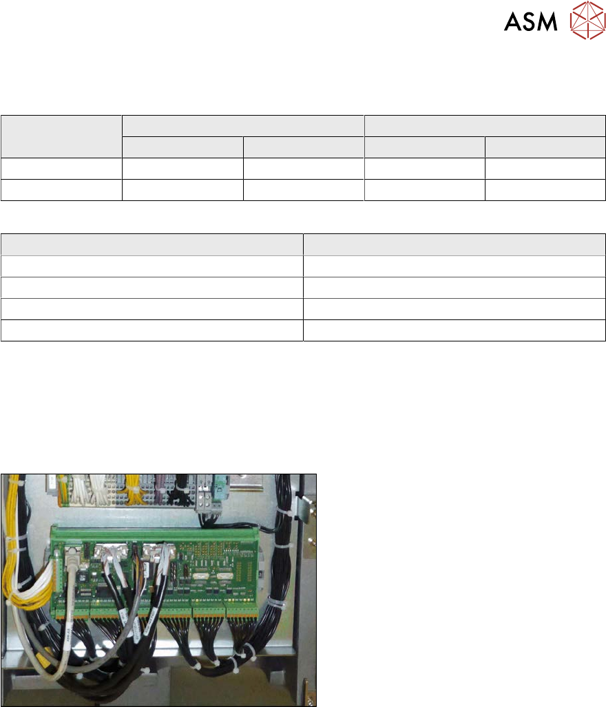
Fig.154: I/O control unit
I/O control unit
The I/O control unit is located between loca-
tion 1 and 2, behind the bottom cover.
See the board description: 4.10.1 "I/O con-
trol unit" [}128]
Removal
► Take a note of the component counter reading at the software user interface.
► Switch off the machine, disconnect it from the power supply and secure it to prevent
unauthorized reactivation.
1.2 "Preparatory work..." [}16]
► Unplug all press-fit connections. You might like to mark their positions to make clear assign-
ment easier later on.
► Pull the I/O control unit out of its mount.
Installation
► Follow the removal instructions in reverse order for installation. Also observe the following
instructions:
– Make sure that the DIP switches are configured correctly (see 4.10.1 "I/O control
unit" [}128]).
– Check if the component counter of the software still matches the value you have written
down. If this is not the case, contact your SIPLACE service team.