00197042-04_SM_X-Serie-S_Customer_EN.pdf - 第323页
8 Head exchange 8.8 Installation Positions on the Head Plate Service Manual SIPLACE X-Serie S 06/2019 323 8.8 Installation Positions on the Head Plate Fig.416: Installation positions on the head plate
8 Head exchange
8.7 Replacing the SIPLACE Twin
322 Service Manual SIPLACE X-Serie S 06/2019
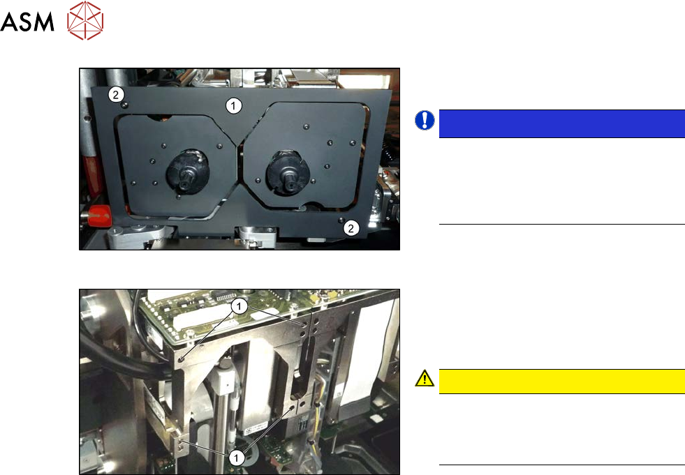
Fig.414: Camera lens hood
► Remove the camera screen(1). This is
fastened with two black screws(2).
NOTICE!
Only use these black screws to fix the
camera lens hood. This prevents re-
flection when measuring components
with the stationary camera.
.
Fig.415: Fastening screws
Each module is fixed with four screws to the
head plate and is positioned with two pins.
► Remove the four M4x14 fastening
screws (1) with a long Allen key.
CAUTION!
Hold tight!
Hold the module tight before removing
the last of the four screws. The module
could otherwise fall down.
.
► Pull the module out of the locating pins.
► Placing the head into the head transport box
Installation
► Follow the removal instructions in reverse order for installation. Also observe the following
instructions:
– Fit the fastening screws on the other side of the module, if needed (see above).
– Make a note of the force values for the new module. These force values can be found on a
label at the side of the module.
– Make sure that the assembly position is correct.
– Perform a head calibration.
1.2 "Preparatory work..." [}16]
5.2 "Disabling the compressed air supply" [}134]
See also
2 8.8 "Installation Positions on the Head Plate" [}323]
2 8.9 "Calibration" [}324]
2 8.9.2 "Calibrating the heads and cameras (SW70x)" [}325]
8 Head exchange
8.8 Installation Positions on the Head Plate
Service Manual SIPLACE X-Serie S 06/2019 323
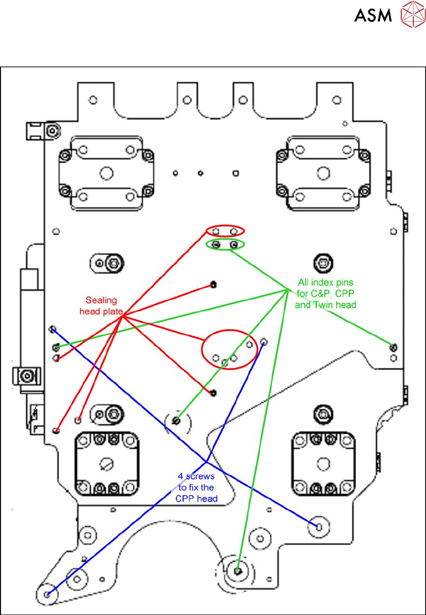
8.8 Installation Positions on the Head Plate
Fig.416: Installation positions on the head plate

8 Head exchange
8.9 Calibration
324 Service Manual SIPLACE X-Serie S 06/2019
8.9 Calibration
Overview
With the calibration of the component camera the following values are determined:
the relationship of "camera pixel size to resolution of machine measuring system (X,Y)", the "cam-
era center point in X and Y direction" and the "torsion angle of the CCD sensor in the camera". This
is following by determining the head offset and the segment offsets for the top and bottom.
●
Head offset: the head offset is the distance between the PCB camera and the nozzle (seg-
ment1). The target is a fixed value (X=0 and Y=‑105mm) to which an offset value (from the
head calibration) is added.
●
Segment offset top: the top segment offset involves turning the calibration tool in the compo-
nent camera in 0°, 90°, 180° and 270°. The value determined is that of the rotating center of
the nozzle tip in relation to the component camera center in the X and Y direction.
●
Segment offset bottom: the bottom segment offset involves recording and measuring the
calibration tool in the 0°, 90°, 180° and 270° positions. The value determined is that of the ro-
tating center point of the nozzle tip when the Z axis is extended in relation to the PCB camera.
Segment 1 is the reference (X=0, °Y=0) for the other segments.
8.9.1 Calibration procedure
► Machine zero point
► PCB camera
– Camera coefficient (illustration scale in nm/pixel)
– Calibration of PCB camera center point
– Calibration of PCB camera rotation to machine coordinate system
► Calibration tool position (optional)
► Travel distance X/Y axis (optional)
– Calibration of min/max gantry travel distances
► Placement head
– Pressure control valve (SIPLACE C&P20P)
– Camera coefficient (unit nm/pixel), angle
– Head offset (offset PCB camera to component camera)
– Segment offset II (bottom)
– Segment offset I (top)
► Nozzle changers
– Calibration of pickup position for all magazines
– Calibration of pickup height
– Calibration of reject position