00197042-04_SM_X-Serie-S_Customer_EN.pdf - 第326页
8 Head exchange 8.9 Calibration 326 Service Manual SIPLACE X-Serie S 06/2019
8 Head exchange
8.9 Calibration
Service Manual SIPLACE X-Serie S 06/2019 325
8.9.2 Calibrating the heads and cameras (SW70x)
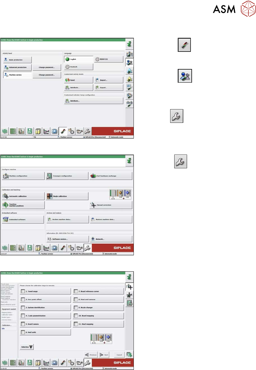
Fig.417: Select operator level
► Select the
button, to open the
Configure, update and calibrate the
machine menu.
► Select the
button to open the
Check and set user settings menu.
► Switch over to the operator level Ma-
chine service.
ð The
button will be shown.
Fig.418: Service Menu
► Click the
button to enter the Ser-
vice menu.
► Click the Automatic calibration but-
ton.
Fig.419: Automatic Calibration
► Select Heads and cameras.
► Click on the Continue button.
Follow the instructions on the next pages:
► On the next page, select the gantries
on which the heads to be calibrated are
located and then click on the Next but-
ton.
► The next step is to check the calibration
conditions (nozzle, calibration tool etc.).
Follow the instructions provided.
After this step, calibration will begin. All re-
quired intermediate steps (head height etc.)
will be performed automatically.

8 Head exchange
8.9 Calibration
326 Service Manual SIPLACE X-Serie S 06/2019
9 Component feeding
9.1 Cutter
Service Manual SIPLACE X-Serie S 06/2019 327
9 Component feeding
DANGER
Observe User Manual
► Please observe the safety instructions in the user manual for all work!
9.1 Cutter
DANGER
Observe User Manual
► Please observe the safety instructions in the user manual for all work!
WARNING
Risk of injury when working near the tape cutter.
When working in the area of the tape cutter, move the component trolley out of the machine
and disconnect the machine from the mains supply and the compressed air supply.
► Wait until the operating pressure has dropped to 0 MPa.
► Always secure the machine against unauthorized reactivation.
► Do not reach into the tape cutter.
CAUTION
Risk of injury when performing service work on the tape cutter.
Never support the tape cutter on your body, e.g., on your knees or thighs. Do not place
your feet under the tape cutter.
► Wear appropriately thick protective gloves.
► When removing/fitting the tape cutter, hold it only outside on the left and right.
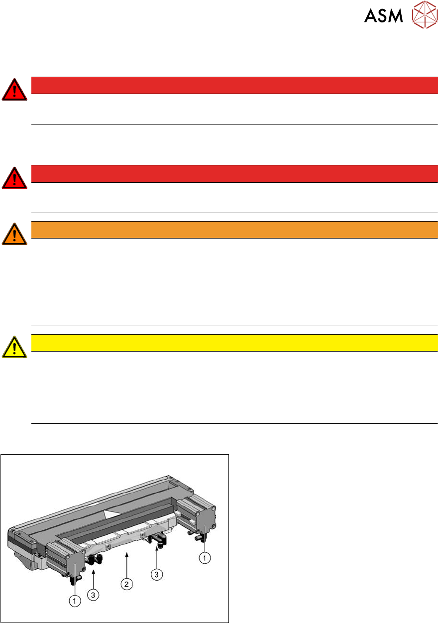
9.1.1 Cutter
Fig.420: Overview of cutter [03066690‑xx]
1. Short stroke cylinder
2. Electrical connection
3. Solenoid valves