00197042-04_SM_X-Serie-S_Customer_EN.pdf - 第62页
3 Power supply 3.4 Power supply and transformer module (up to serial number Gxxx) 62 Service Manual SIPLACE X-Serie S 06/2019 3.4.9 Replacing the Rectifiers (U1 to U3, U20 to U24) Parts, equipment and tools ● U1, U3: rec…
3 Power supply
3.4 Power supply and transformer module (up to serial number Gxxx)
Service Manual SIPLACE X-Serie S 06/2019 61
3.4.8.1 Setting the Voltage on the AC/DC Converters
Parts, equipment and tools
●
Voltage measuring device
Overview
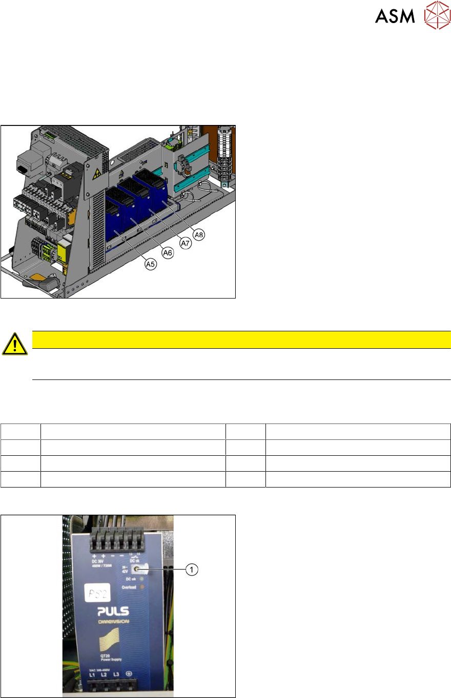
Fig.60: AC/DC converter
The AC/DC converters are located in the
rack unit between location 3 and 4.
A5) AC/DC converter (24 VDC, set to 25
VDC)
for Power Fail, safety circuit SSK, tape cut-
ter, PCB handling
The power fail signal is generated by the
AC/DC converter A5 and sent to the GCU
and HCU. (X200:9, X200:10)
A6) AC/DC converter (27 VDC)
for FCU (gantry 1 and 4)
A7) AC/DC converter (27 VDC)
for FCU (gantry 2 and 3)
A8) AC/DC converter (36 VDC, set to 42
VDC)
for HCU (gantry 1 to 4)
CAUTION
Check the values
► Check the set values and correct if necessary.
To A5:
There is 24V present at the following fuses:
F10 Conveyor electrics F11 Y motor fan, safety circuit (internal)
F12 Distributor power (line 1) F13 Distributor power (line 2)
F14 Power fail F20 Cover fan gantry 1 and 4
F21 Cover fan gantry 2 and 3
Setting
Fig.61: Setting the voltage
► Open the protective cap on the setting
screw(1).
► Use a flat-bladed screwdriver to set the
correct voltage on the AC/DC con-
verter.
Check the voltage with a suitable
voltage measuring device between the
terminals + and–.
3 Power supply
3.4 Power supply and transformer module (up to serial number Gxxx)
62 Service Manual SIPLACE X-Serie S 06/2019
3.4.9 Replacing the Rectifiers (U1 to U3, U20 to U24)
Parts, equipment and tools
●
U1, U3: rectifier S101-B6U 160-08 [00341246-xx]
●
U2: rectifier S61-B2U 28-10 [03080931-xx]
●
U20 to U24: rectifier S61-B2U 28-04 [03079959-xx]
●
Silicon-free heat-conductive paste (not electrically conductive)
Thermal conductivity 1.0 W/mK
Dielectric strength 40kV/mm
Temperature range -40°C to +200°C
Flash point >280°C
Suggested supplier: Bürklin OHG, order number 80 B 531
Overview
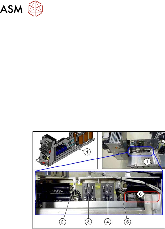
Fig.62: Rectifiers
1. Cover
2. Rectifier U24
3. Rectifier U3
4. Rectifier U1
5. Rectifier U2
6. Rectifier U20 to U23
Removal
► Switch off the machine, disconnect it from the power supply and secure it to prevent
unauthorized reactivation.
1.2 "Preparatory work..." [}16]
► Before you start working, check the power supply for absence of voltage and observe the
waiting times!
► Remove the screws fastening the cover and swing the cover towards the front. The AC/DC
converters are also fitted on the cover. These are swung away with the cover.
► Unplug all connections to the rectifiers. You may want to mark their positions, to make clear
assignment easier later on.
► Remove the screws fastening the rectifier and remove the rectifier.
Installation
► Follow the removal instructions in reverse order for installation. Also observe the following
instructions:
– Apply a heat-conductive paste between the metal frame and the rectifier.
3 Power supply
3.4 Power supply and transformer module (up to serial number Gxxx)
Service Manual SIPLACE X-Serie S 06/2019 63
3.4.10 Replacing the load add circuit (A4)
Parts, equipment and tools
●
FBG dyn. load add circuit intermediate cycle [03094585Sxx]
(replaces: LZS260/1000 [03061114-xx])
Overview
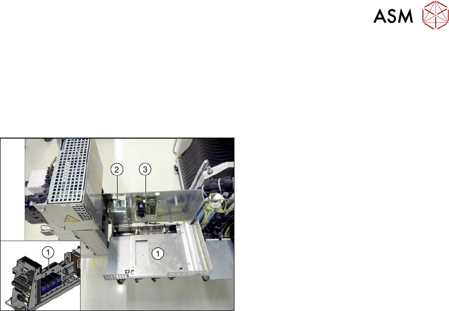
Fig.63: Overview of line filter and load add circuit
1. Cover
2. Line filter (Z1)
3. Load add circuit (A4)
Removal
► Switch off the machine, disconnect it from the power supply and secure it to prevent
unauthorized reactivation.
1.2 "Preparatory work..." [}16]
► Before you start working, check the power supply for absence of voltage and observe the
waiting times!
► Remove the screws fastening the cover and swing the cover towards the front. The AC/DC
converters are also fitted on the cover. These are swung away with the cover.
► Unplug all connections to the load add circuit. You might like to mark their positions to make
clear assignment easier later on.
► Remove the screws fastening the load add circuit and remove the load add circuit.
Installation
► Follow the removal instructions in reverse order for installation.