00197042-04_SM_X-Serie-S_Customer_EN.pdf - 第314页
8 Head exchange 8.5 Replacing the SIPLACE C&P20P/M2 314 Service Manual SIPLACE X-Serie S 06/2019 Overview Fig.398: SIPLACE C&P20P 1. Holding circuit connection 2. Intermediate distributor board (behind the cov…

8 Head exchange
8.5 Replacing the SIPLACE C&P20P/M2
Service Manual SIPLACE X-Serie S 06/2019 313
8.5 Replacing the SIPLACE C&P20P/M2
NOTICE
Vacuum test
► If required, perform a vacuum test before removing the placement head.
Read the "Service manual Vacuum test at C&P placement head" [DE+EN:
00196101‑xx] for this.
NOTICE
Prerequisites for the SIPLACE C&P20P
The following additional conditions must be fulfilled for operating a SIPLACE C&P20P:
► Head interface - at least function state [03091013-03] / [03091023-03]
► Base adapter - minimum function state [03055516-06] / [03045647-08]
► MHCU – at least function state [03090990-03]
► Nozzle changers [03103649-xx] must be used.
► Nozzle station - at least function state [03073328-02]
NOTICE
Fast Hardware Exchange (FHE)
► Observe the instructions in section 8.1 "Fast Hardware Exchange" [}305] when ex-
changing a head.
Parts, equipment and tools
●
SIPLACE C&P20P [03091157‑xx] (without camera)
●
SIPLACE C&P20M2 [03125907Sxx] (without camera)
NOTICE
Vacuum pump/compressed air operation
As a spare part, the head is prepared for vacuum pump operation.
► Convert the placement head for compressed air operation using the "Hold-circuit com-
plete/C&P20" [03005123Sxx] kit.
●
Torx screwdriver ESD 1.0-5.0 Nm [03078400-xx]
●
Bit holder for TorqueVario screwdriver [03078706-xx]
●
Extension/straight TX20 [03073256-xx]
●
Torx offset screwdriver TX8 [03080081-xx]
Fig.397: Component sensor protective cap [03092400‑xx]
●
Component sensor protective cap
[03092400‑xx]
●
Calibration tool version SST23 [03034148-xx]
For additional work to the placement head:
●
Head mount [03056231‑xx]
●
Service manual "SIPLACE C&P20P head" [DE:00197489‑xx] [EN:00197490‑xx]
●
Job Card "Preventive Maintenance C&P20P" [DE:00197529‑xx] [EN:00197528‑xx] (other
languages available)
●
If required, for vacuum pump operation: Assembly instructions "Vacuum pump SIPLACE X-
Series S, SX4/DX4" [00196845-xx]
8 Head exchange
8.5 Replacing the SIPLACE C&P20P/M2
314 Service Manual SIPLACE X-Serie S 06/2019
Overview
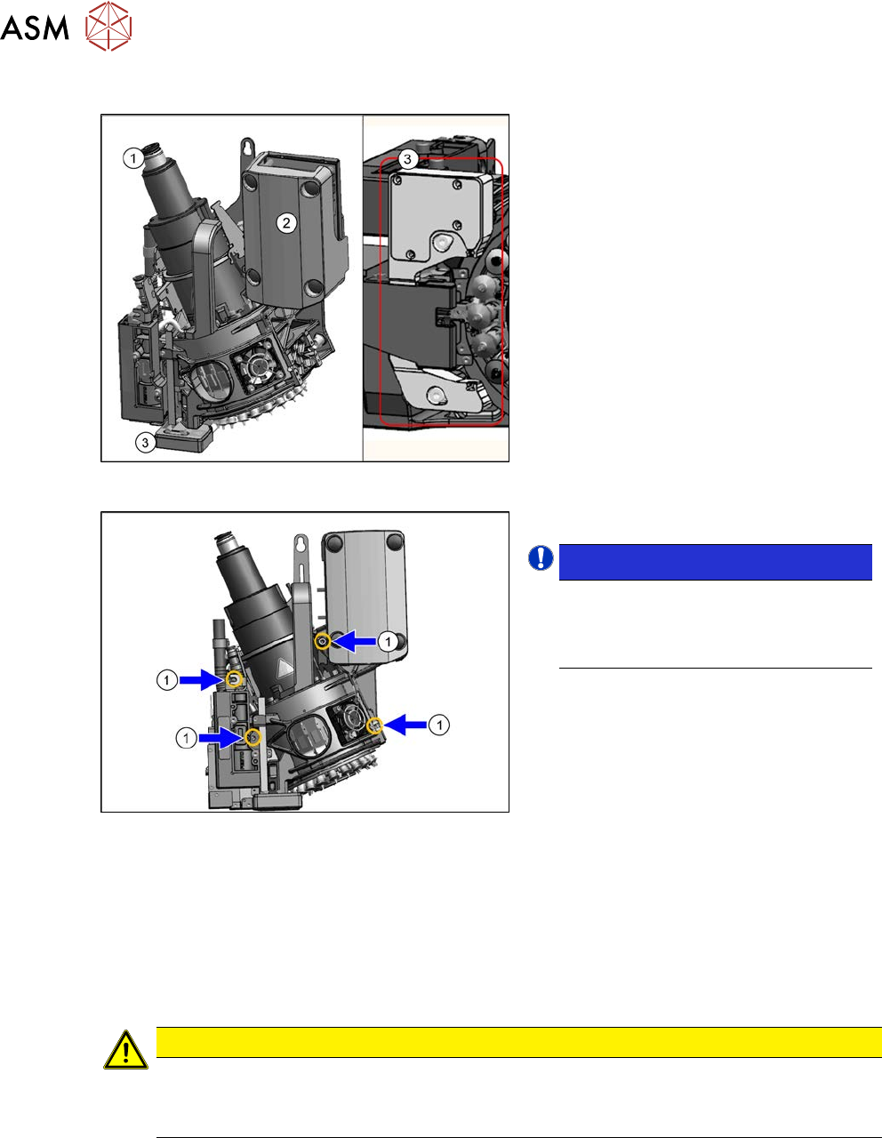
Fig.398: SIPLACE C&P20P
1. Holding circuit connection
2. Intermediate distributor board (behind
the cover)
3. Component sensor
Fig.399: Fastening screws
1. Four fastening screws (yellow marks)
NOTICE!
The length of the exhaust air hose "Sil-
icon hose Di8 Da12 electrically con-
ductive 1m" [03006727Sxx] on the
SIPLACE C&P20P/M2 is 355mm.
.
Removal
► Switch off the machine, disconnect it from the power supply and secure it to prevent
unauthorized reactivation.
1.2 "Preparatory work..." [}16]
► Switch off the compressed air supply
5.2 "Disabling the compressed air supply" [}134]
CAUTION
Take great care when dismantling the placement head!
The component sensor prisms, underneath the placement head, could be damaged.
► Never place the placement head down on the component sensor.
► Fit the protective cap onto the component sensor for the placement head.
8 Head exchange
8.5 Replacing the SIPLACE C&P20P/M2
Service Manual SIPLACE X-Serie S 06/2019 315
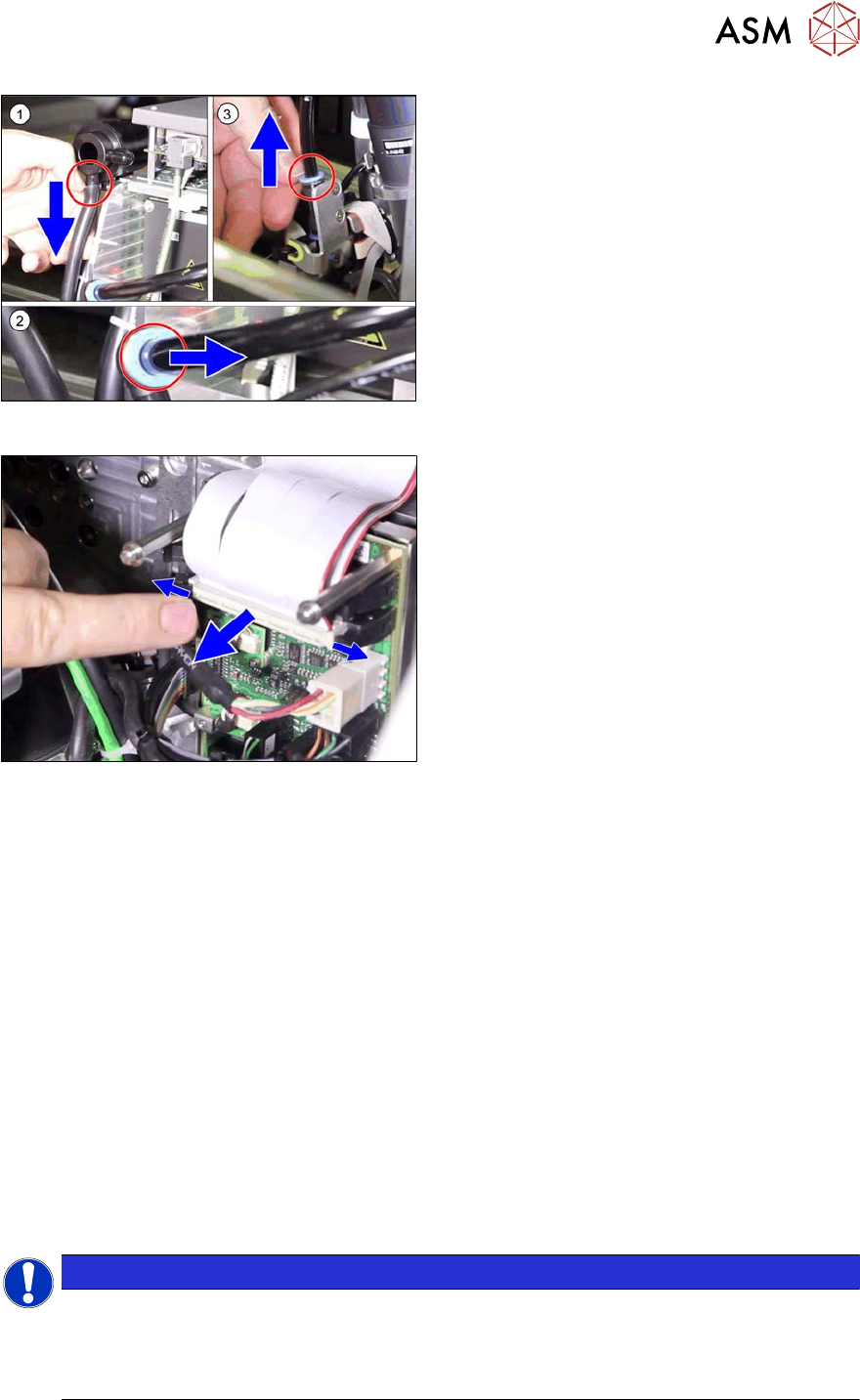
Fig.400: Pneumatic connections
► Disconnect the pneumatic connec-
tions(1) to(3) from the placement
head.
Fig.401: Flat ribbon cable
► Unplug the ribbon cables between the
placement head and the head adapter.
► Remove the screws fastening the strain relief on the component camera cables of the head
interface and carefully unplug the cables. While unplugging the cables, press the clamps on
both sides of the connectors.
► Unscrew all four M4 fastening screws with a long Torx key.
► Carefully lift the placement head out of the locating pins on the head plate and from the hook.
► Placing the head into the head transport box
Installation
► Follow the removal instructions in reverse order for installation. Also observe the following
instructions:
– If you replace the placement head without the component camera, you will need to fit the
old camera into the new head. In this case a full calibration is necessary. Read the service
manual for your placement head for more information.
– For compressed air mode, the placement head must be converted using the "Hold circuit
assembly/C&P20" [03005123Sxx].
– Make sure that the assembly position on the head plate is correct.
– Tighten the four head fastening screws (M4) with a torque of 2.7 Nm.
NOTICE
Various hose lengths on SIPLACE X-Series S
The hose to the pressure control valve will vary in length, depending on the installation loc-
ation (standard gantry or rotated gantry).
► Shorten or replace the hose, where necessary.
See also
2 8.8 "Installation Positions on the Head Plate" [}323]