00197042-04_SM_X-Serie-S_Customer_EN.pdf - 第268页
7 Conveyor 7.8 Laser light barriers, fiber optic cable and PCB sensors 268 Service Manual SIPLACE X-Serie S 06/2019 Overview Fig.337: Overview of conveyor controls The cables for the laser light barriers are either conn…
7 Conveyor
7.8 Laser light barriers, fiber optic cable and PCB sensors
Service Manual SIPLACE X-Serie S 06/2019 267
Sensor cable
Part to be replaced Correct spare part
[03088545‑xx] Sensor cable belt motor input lane 1 L=760 mm Sensor cable belt mo-
tor input lane 2
L=2180 mm
[03088871‑xx]
[03088547‑xx] Sensor cable belt motor placement position 1 lane 1
L=1680 mm
[03088549‑xx] Sensor cable belt motor intermediate position lane 1
L=1500 mm
[03088551‑xx] Sensor cable belt motor placement position 2 lane 1
L=1680 mm
[03088552‑xx] Sensor cable belt motor output lane 1 L=760 mm
[03088553‑xx] Sensor cable belt motor input lane 2 L=760 mm
[03088554‑xx] Sensor cable belt motor placement position 1 lane 2
L=1680 mm
[03088555‑xx] Sensor cable belt motor intermediate position lane 2
L=1220 mm
[03088556‑xx] Sensor cable belt motor placement position 2 lane 2
L=1690 mm
[03088557‑xx] Sensor cable belt motor output lane 2 L=760 mm
[03092519‑xx] Sensor cable W51 laser side panel C2 L=1530 mm Sensor cable W46
laser side panel C1
L=1630 mm
[03092514‑xx]
[03088491‑xx] Sensor cable W30 sensor 1 side panel B1 L=1220 mm Sensor cable W41
sensor 1 side panel
B2 L=2170
[03088495‑xx]
[03088492‑xx] sensor cable W31 sensor 2 side panel B1 L=1590 mm
[03088496‑xx] sensor cable W42 sensor 2 side panel B2 L=1660 mm
Other cables
Part to be replaced Correct spare part
[03092517‑xx] Cable W49 side panel D1 sensor LLB1 L=1360 mm Cable PCB centering
receiver LLB2
L=1850 mm
[03088522‑xx]
[03092518‑xx] Cable W50 side panel D1 sensor LLB2 L=1020 mm
[03093772‑xx] Cable W69 side panel D2 sensor LLB1 L=950 mm
[03093773‑xx] Cable W70 side panel D2 sensor LLB2 L=1420 mm
[03088490‑xx] Cable W21 side panel A1 laser LLB1, LLB2 L=940 mm Cable PCB centering
LLS1, LLS2, L=1860
mm [03088856‑xx]
[03088493‑xx] Cable W43 side panel A2 laser LLB1, LLB2 L=1360 mm
NOTICE
Labeling the cable
► Label the new cable identically to the cable which is to be replaced. If the cable is too
long, stow the excess length in the conveyor base, near the connection. Fix the cables
with a cable tie, where necessary.
7 Conveyor
7.8 Laser light barriers, fiber optic cable and PCB sensors
268 Service Manual SIPLACE X-Serie S 06/2019
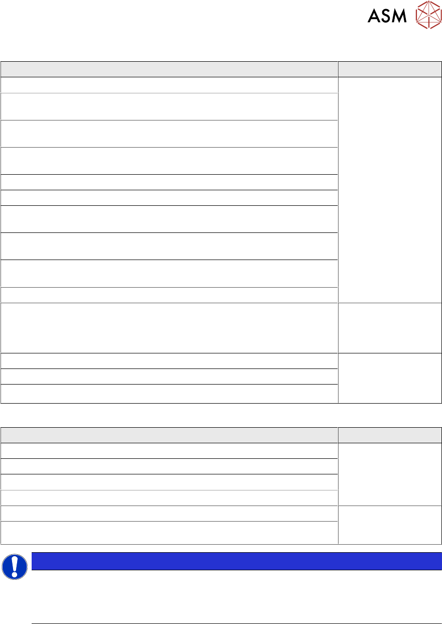
Overview
Fig.337: Overview of conveyor controls
The cables for the laser light barriers are
either connected directly to the conveyor
controls(1) or to the input or output area(2)
of the conveyor.
For details of the conveyor control, see
7.9.1.1 "Conveyor control TSP420" [}291].
Removal
► Switch off the machine, disconnect it from the power supply and secure it to prevent
unauthorized reactivation.
1.2 "Preparatory work..." [}16]
CAUTION
Move the conveyor sides carefully!
The clamping and guide rails are a key stabilizing element for the conveyor side, which is
then less stable once they have been removed.
► Move the opened conveyor sides very carefully.
► Make sure that the sides are always pushed equally on the left and right.
► Make sure that you do not distort the sides.
CAUTION
Make a note of the order in which the cables are run!
The room in the side walls is limited. Therefore, make sure that no cables are crossed over,
particularly in the output area, from the trailing cable to the laser light barrier.
Make a note of the order in which the cables are run in the side panel, so that you can run
them neatly and correctly again later on.
► Remove the transmitter/receiver.
7.8.1 "Replacing the Laser Light Barrier for the Transmitter/Receiver" [}263]
► You might need to dismantle other guide rails in order to thread the cable out of the conveyor
side, as far as the trailing cable.
7.7.3 "Replacing the Clamping Rail/Belt Guidance" [}259]
► You might want to move hexagonal shafts in order to create more room for movement.
7.6.6 "Replacing the hexagonal shaft" [}253]
7 Conveyor
7.8 Laser light barriers, fiber optic cable and PCB sensors
Service Manual SIPLACE X-Serie S 06/2019 269
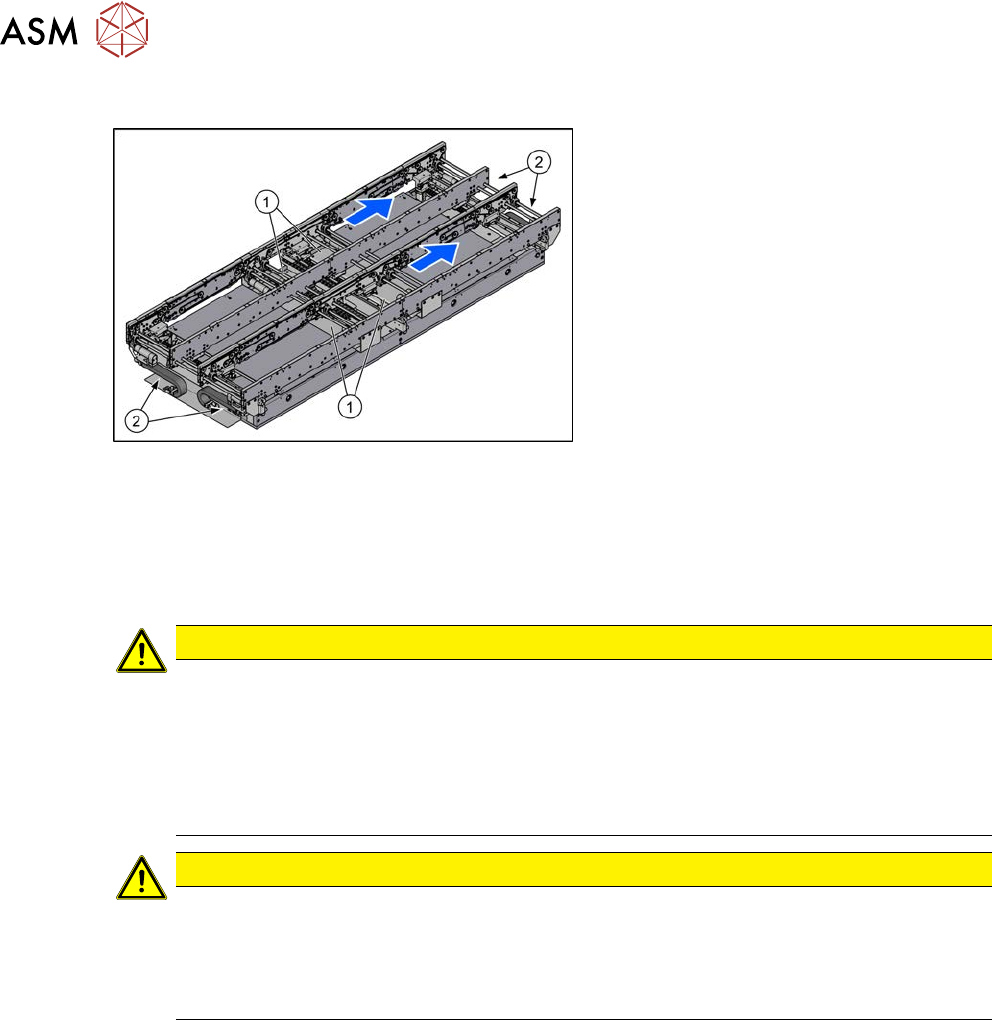
Fig.338: Holding plate
► Remove the screws(2) fastening the
bracket(3) to the top end of the trailing
cable(1) on the conveyor side.
► For better access, you can remove the
screws fastening the trailing cable to
the bracket.
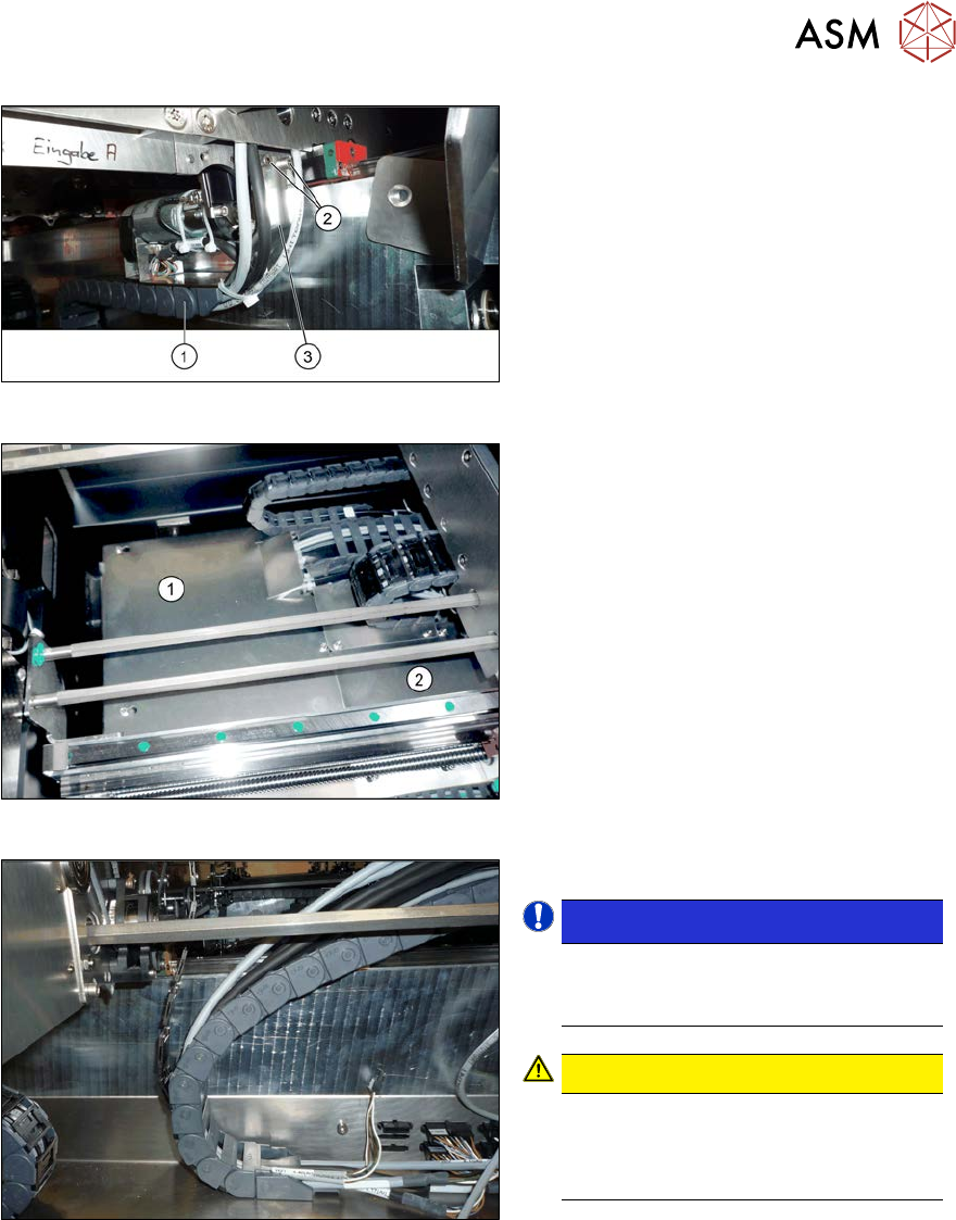
Fig.339: Cover plates (example of SX1/SX2 shown)
► In the intermediate conveyor: dismantle
the two cover plates(1) and (2) under
the trailing cable. To do this, loosen the
four fastening screws for each and then
remove the cover plates.
Fig.340: Opened trailing cable
► Open the trailing cable.
NOTICE!
There is also a protective tape in the
trailing cable. This separates the fiber
optic cable from the cables.
.
CAUTION!
Make sure you do not bend the fiber
optic cable. These could otherwise be-
come cloudy or break and no longer
transmit the signal properly.
.
► For better access, you can remove the
screws fastening the trailing cable to
the bottom of the conveyor.
► Thread the cable out of the conveyor
side and the trailing cable.