00197042-04_SM_X-Serie-S_Customer_EN.pdf - 第274页
7 Conveyor 7.8 Laser light barriers, fiber optic cable and PCB sensors 274 Service Manual SIPLACE X-Serie S 06/2019 7.8.5 Replacing the fiber optic cable NOTICE Repairing the Fiber Optic Cable Depending on the machine an…
7 Conveyor
7.8 Laser light barriers, fiber optic cable and PCB sensors
Service Manual SIPLACE X-Serie S 06/2019 273
7.8.4 Correcting the Laser Light Barrier Setting
DANGER
Laser class 2
The laser light barrier transmitter emits class 2 laser beams. You therefore do not require
additional protective measures!
► However, you should never look into the laser beam!
► Adjust the laser beam only from the rear side of the laser!
Parts, equipment and tools
●
Recommendation for new version of receiver (silver receiver surface):
semi-transparent paper or plastic (for better recognition of laser beam)
Overview
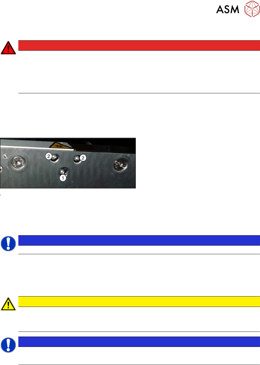
Fig.348: Laser light barrier
1. Fastening screw
2. Setting screws
Procedure
► Set the maximum conveyor width.
NOTICE
Deviation of the laser beam has the greatest effect at maximum conveyor width.
► Select "Enable safety mode".
► Activate the relevant laser diode using the input/output functions in the station software.
► Use the top two screws to set the laser beam so that it is correctly aligned with the laser recei-
ver.
CAUTION
Screws on the laser transmitter
► Hand-tighten the lower screw. The top two screws are used to set the laser beam.
These may not be fully tightened, otherwise the laser transmitter could be damaged.
NOTICE
Semi-transparent paper or plastic
► Use semi-transparent paper or plastic to make the laser beam visible on the receiver.
► Now position the conveyor to minimum width and check the setting,
► Check the PCB reference corner and reteach, if necessary.
7 Conveyor
7.8 Laser light barriers, fiber optic cable and PCB sensors
274 Service Manual SIPLACE X-Serie S 06/2019
7.8.5 Replacing the fiber optic cable
NOTICE
Repairing the Fiber Optic Cable
Depending on the machine and the installation position, the complete replacement of the
fiber optic cable may take approx. 2 to 2.5 hours. To avoid downtimes, it is possible to per-
form a short-term repair using the repair hose. Observe the instructions in section 7.8.6
"Repairing the fiber optic cables" [}278].
Parts, equipment and tools
●
Fiber optic cable LL3-TV05 3 m [03092408-xx]
(two fiber optic cables per pack incl. cutter tool)
NOTICE
Transmitter/receiver:
Both fiber optic cables are technically identical and be used either as transmitters or receiv-
ers.
Overview
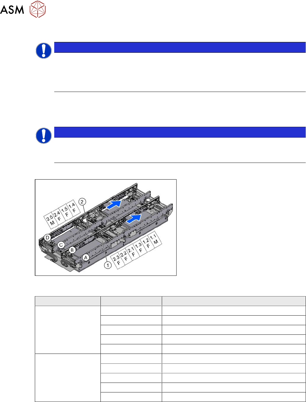
Fig.349: Overview of fiber optic cable sensor
The fiber optic cable sensors are located at
locations 1 and 4, under the covers of the
conveyor control(1) and(2).
The sensors for the input conveyor, place-
ment area 1 and intermediate conveyor can
be found at (1).
The sensors for placement area 2 and the
output conveyor can be found at (2).
The fiber optic cable sensors are separated
into master (M) and slave (F).
The receiver is always at the top of the
sensors and the transmitter at the bottom.
The transmitters are located on sides B and
D.
The receivers are located on sides A and C.
Conveyor lane Designation Location
Lane 1 1.1 Input belt
1.2 Placement area 1
1.3 Intermediate belt
1.4 Placement area 2
1.5 Output belt
Lane 2 2.1 Input belt
2.2 Placement area 1
2.3 Intermediate belt
2.4 Placement area 2
2.5 Output belt
7 Conveyor
7.8 Laser light barriers, fiber optic cable and PCB sensors
Service Manual SIPLACE X-Serie S 06/2019 275
Troubleshooting
The following points indicate that there are problems with the fiber optic cables:
●
Boards are shown in the conveyor, although there are none there.
●
The fiber optic cables are not illuminated on the transmitter side.
●
The fiber optic sensor (at the conveyor control) shows a value of zero.
●
If the fiber optic cable sensor shows nothing, this indicates that there could be a problem with
the sensor.
Try the following steps to remedy the problem:
► Refresh the PCB status.
► Teach the PCB sensors.
NOTICE
Fiber optic cable sensor
If you replace the fiber optic cable transmitter and receiver on the fiber optic sensor, you
can check at the "receiver end" whether the fiber optic cable is OK. The transmitter should
be illuminated.
Removal
CAUTION
Do not bend the fiber optic cable
► Make sure you do not bend the fiber optic cable. These could otherwise become
cloudy or break and no longer transmit the signal properly.
CAUTION
Move the conveyor sides carefully!
The clamping and guide rails are a key stabilizing element for the conveyor side, which is
then less stable once they have been removed.
► Move the opened conveyor sides very carefully.
Make sure that the rails are always pushed equally on the left and right.
Also make sure that you do not distort the rails.
► Switch off the machine, disconnect it from the power supply and secure it to prevent
unauthorized reactivation.
1.2 "Preparatory work..." [}16]
► Dismantle the clamping or guide rail on the fiber optic cable.
7.7.3 "Replacing the Clamping Rail/Belt Guidance" [}259]
► Loose the screw fastening the fiber optic wire to the clamping or guide rail. The fiber optic wire
is either fixed with a nut (M5.5) or a grub screw, depending on the installation location.
► You may want to dismantle more clamping and guide rails so that you can thread the fiber op-
tic cable out of the trailing cable. You might also need to dismantle the transmitter/receiver for
the laser light barrier.
7.8.1 "Replacing the Laser Light Barrier for the Transmitter/Receiver" [}263]
► You might want to move hexagonal shafts in order to create more room for movement.
7.6.6 "Replacing the hexagonal shaft" [}253]