00197042-04_SM_X-Serie-S_Customer_EN.pdf - 第381页
9 Component feeding 9.4 Docking Station for Component Trolley Service Manual SIPLACE X-Serie S 06/2019 381 9.4.2 Replacing the power pack NOTICE Observing the technical information ► Observe the technical information &qu…
9 Component feeding
9.4 Docking Station for Component Trolley
380 Service Manual SIPLACE X-Serie S 06/2019
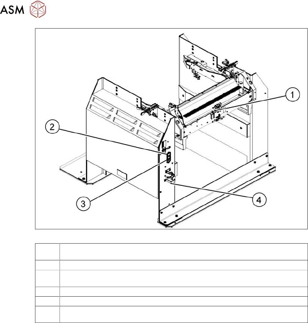
Fig.510: Docking station – back
1 Control valve [03003489-xx]
9.4.11 "Replacing the control valve" [}394]
2 ON/OFF switch
3 Microfuse [03033387-xx]
9.4.3 "Replacing the micro switch" [}382]
4 Pressure control valve for bulkcase feeder and main connection (5.5 bar)
9.4.6 "Replacing the positions end switch of the component trolley locking device" [}386]
9.4.9 "Replacing the Complete Coupling - Earthing and Compressed Air for the Bulk
Case" [}391]
9 Component feeding
9.4 Docking Station for Component Trolley
Service Manual SIPLACE X-Serie S 06/2019 381
9.4.2 Replacing the power pack
NOTICE
Observing the technical information
► Observe the technical information "Power pack for docking station for component trol-
ley SIPLACE X [116933] and SX [116965] has been discontinued" [DE: TI2015-04D07]
[EN: TI2015-04E07].
Parts
03121806‑xx Switching power supply RSP-500-27 (replaces: [03025938‑xx])
Equipment and tools
00353832-xx Allen key set
Wire cutters
Cable ties
Voltage measuring device
00198460‑xx Detailed circuit diagrams folder SIPLACE TX V2-Series
Removal / installation
DANGER
Switch off the voltage supply
► Press the ON/OFF button to switch off and disconnect the power supply.
4
3
1
3
2
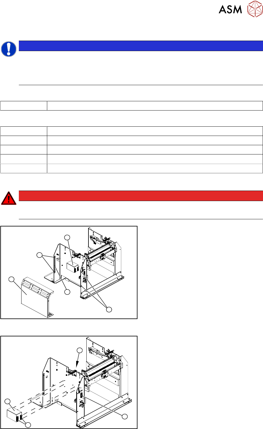
Fig.511: Removing the cover
The power pack(4) is located behind the
cover(1).
► Remove the four screws(3) fastening
the cover. The cover is clamped in
place with the help of the bar(2).
► Pull the cover out of the docking sta-
tion.
Pay attention to the ground connection.
4
3
1
2
Fig.512: Removing the power pack
► Disconnect all electrical connections(4)
to the power pack(3). You may want to
mark their positions to make clear as-
signment easier later on.
► Remove the four screws(2) fastening
the power pack and then remove the
power pack.
► Connect all cables and fit the new
power pack.
► Press the ON/OFF button(1) to switch
on.
9 Component feeding
9.4 Docking Station for Component Trolley
382 Service Manual SIPLACE X-Serie S 06/2019
► Set the output voltage of the power pack to 26.8 V at terminals nine and twelve:
– Standard (without BulkFeeder):
26.8 V (+/- 0.5 V)
– When using the BulkFeeders the output voltage is set permanently to 28.0V(+/‑0.5V).
► Refit the cover.
9.4.3 Replacing the micro switch
Parts
03033387‑xx Microfuse
Overview
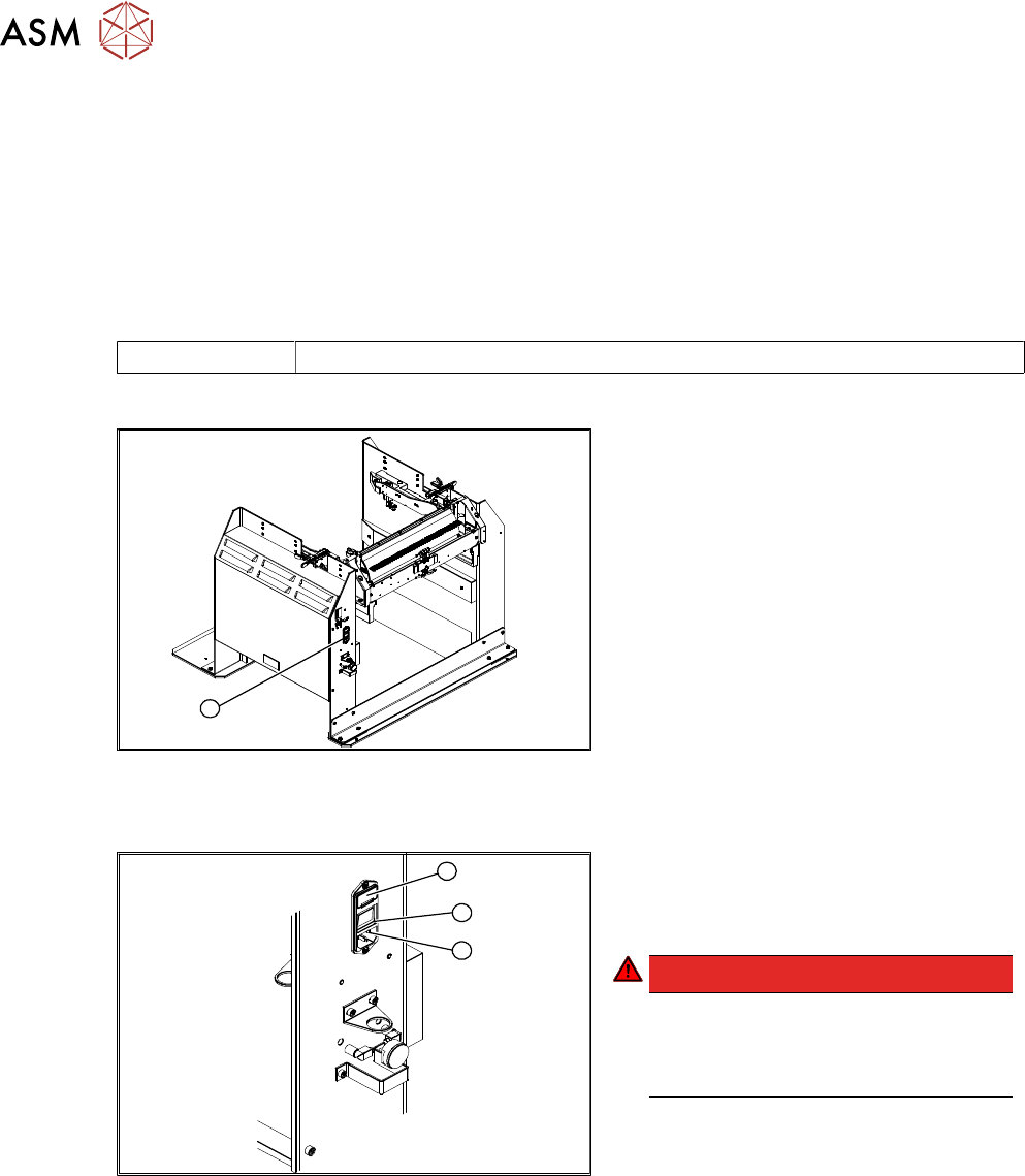
1
Fig.513: Microfuse on docking station
1. Position of microfuse (T 8.0 A)
Replacing the microfuse
1
3
2
Fig.514: Replacing the microfuse
1. Cover on the microfuse (T8.0A)
2. ON / OFF switch
3. Power supply plug
DANGER!
Switch off the voltage supply
Press the ON/OFF button (2) to switch
off and then unplug the power supply
(3).
.
► Open the cover (1) on the microfuse.
► Remove the microfuse.
► Insert the new microfuse and close the cover (1).
► Connect the connection cable (3) and press the ON/OFF button to switch on (2).