00197042-04_SM_X-Serie-S_Customer_EN.pdf - 第134页
5 Pneumatic System 5.2 Disabling the compressed air supply 134 Service Manual SIPLACE X-Serie S 06/2019 5.2 Disabling the compressed air supply Fig.162: Disabling the compressed air supply (version 1) CAUTION! Switch …
5 Pneumatic System
5.1 Pneumatic System - Overview
Service Manual SIPLACE X-Serie S 06/2019 133
5 Pneumatic System
DANGER
Observe User Manual
► Please observe the safety instructions in the user manual for all work!
CAUTION
Switch off the compressed air supply
When working on the pneumatic system, always disconnect the machine from the com-
pressed air supply.
CAUTION
Use the correct blanking plugs
► Only use blanking plugs in the machine which match the manufacturer's compressed
air connection. A tight fit cannot be guaranteed for other blanking plugs.
► We recommend the use of blanking plugs made by Festo.
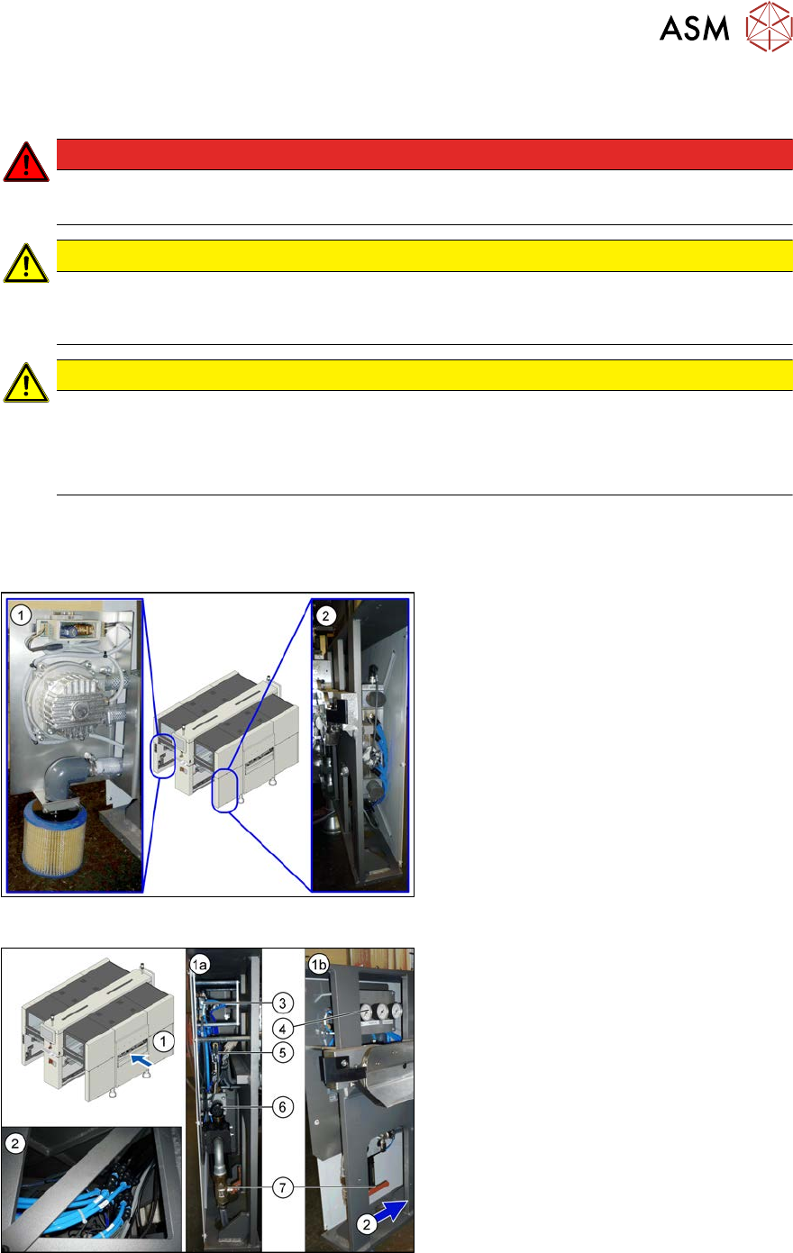
5.1 Pneumatic System - Overview
The pneumatic system is located at locations 1, 3 and 4, behind the side covers.
Fig.160: Pneumatics (location 3 and 4)
1. Location 3, behind the side cover:
Elmo blower with electrics, cooling air
filter
2. Location 4, behind the side cover:
Proportional controller for gantry group
placement heads PA1/PA2
Fig.161: Pneumatics (location 1)
1. Location 1, behind the side cover:
1a) View from front
1b) View from side
Connection coupling, main valve with com-
pressed air filter, compressed air displays
2. Location 1, at the bottom, in the machine
base: compressed air connection for
gantry trailing cable and vacuum pump
3. 5/2 way valve [03062277-xx]
Main valve (X59) for NC, insert, conveyor
4. Manometer
5. 5/2 solenoid valve [00344974-xx]
Safety valve (X60) for tape cutter
6. Pressure regulator [03062103-xx]
7. Main valve
5 Pneumatic System
5.2 Disabling the compressed air supply
134 Service Manual SIPLACE X-Serie S 06/2019
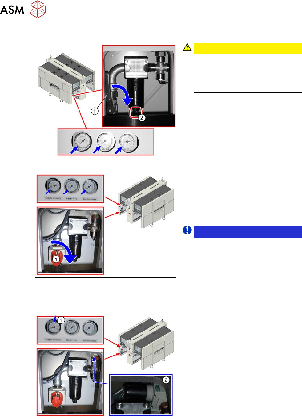
5.2 Disabling the compressed air supply
Fig.162: Disabling the compressed air supply (version 1)
CAUTION!
Switch off the compressed air sup-
ply
The compressed air supply must al-
ways be switched off for all work on
the pneumatic system.
.
Version 1:
► Push the lever (1) for the compressed
air supply down until it is positioned ho-
rizontally.
► Open the screw (2) on the inlet filter to
vent the system. Hold a cloth under-
neath to capture any escaping liquid.
Fig.163: Shutting off the compressed air supply (version 2)
Version 2:
► Push the switch (1) for the compressed
air supply by 90 degrees, until it is posi-
tioned horizontally.
► All pressure gauges must be set to
zero.
NOTICE!
Venting is performed automatically
in this version.
.
5.3 Setting the pressure for the machine components
Fig.164: Pressure for machine components
► Make sure that the pressure for
machine components is set to
5.1bar(1).
► Correct the pressure where necessary,
with the pressure control valve(2).
5 Pneumatic System
5.4 Sealing the Pneumatic Screwed Connections
Service Manual SIPLACE X-Serie S 06/2019 135
5.4 Sealing the Pneumatic Screwed Connections
NOTICE
Sealing the pneumatic screwed connections
If pneumatic screwed connections are loosened, these will need to be sealed again after-
wards. Always use the same sealing technique as was used before they were removed.
The following sealing techniques are available:
► Sealing ring (rubber or plastic)
These are either supplied or you can use the ones used before. Check the condition of
used sealing rings for damage.
► Sealant
There are several variants of this:
Loctite 567 [03097172-xx] and Loctite 55 [03092492-xx]
After loosening the pneumatic screwed connection, clean the screwed thread and seal
it with Loctite. The sealing thread for Loctite 55 must be wound on in the direction of
the screwed thread.
There may also already be a sealant on the screwed thread.
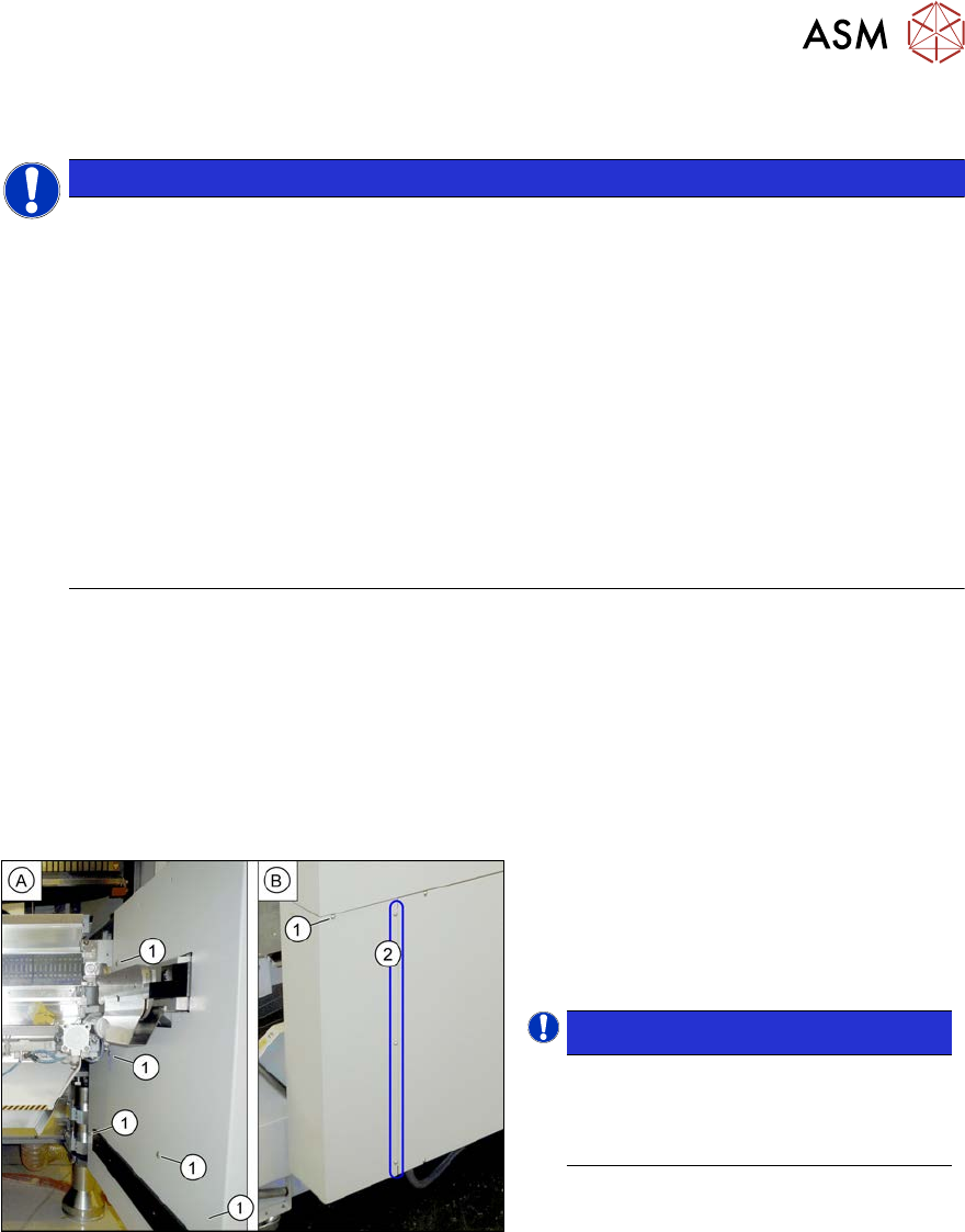
5.5 Dismantling the Lower Side Cover
Most tasks require that you dismantle the lower side cover from the location. This is shown below
using the example of location 2. The procedure for other locations is identical.
Parts, equipment and tools
●
Shortened Allen key, if required
Dismantling the side cover
Fig.165: Dismantling the lower side cover
► While unscrewing, always hold on to
the side cover, to prevent it falling off.
► Remove the six screws(1) fastening
the inner(A) and outer side(B) of the
side panel.
NOTICE!
The three fastening screws (2) on the
outer side are loosened as a default.
The side cover can be pulled out here.
.
► Remove the side cover.
Fitting the side cover
► Assembly is performed by following the above instructions in the reverse order.