00197042-04_SM_X-Serie-S_Customer_EN.pdf - 第245页
7 Conveyor 7.5 Width Adjustment, Clamps and Cylinder Unit Service Manual SIPLACE X-Serie S 06/2019 245 7.5.13 Calibrating the adjustment unit NOTICE This chapter is valid for machines with dual conveyor (DC) only. After …
7 Conveyor
7.5 Width Adjustment, Clamps and Cylinder Unit
244 Service Manual SIPLACE X-Serie S 06/2019
Troubleshooting
NOTICE
Conveyor side was not correctly recognized
► Set the distance between the sensor flag and the adjustment unit so that it is smaller:
0.25 to 0.20mm.
NOTICE
Insufficient clamping power
If the conveyor side clamps are no longer clamping enough, this could be because the con-
veyor side has been moved without the brakes (clamps) being released. In this case, pro-
ceed as follows:
► Remove the clamping unit and check its friction surface. If this is no longer rough,
clean the surface with "universal sanding cleaner". Carefully remove any aluminum
shavings on the friction surface.
► Readjust the clamps as described above and then tighten the screws with 8 Nm.
► If you are unable to set the parallelism of the conveyor sides with the width adjust-
ment, inform your SIPLACE service team.
7.5.12 Replacing the contact plate of the clamping unit
Parts, equipment and tools
●
Contact plate clamp unit SXa [03092536-xx]
●
Eraser, if needed
Overview
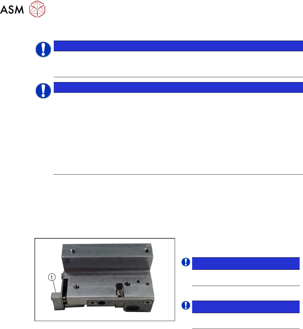
Fig.312: Contact plate
1. Contact plate
NOTICE!
The contact plate is the same through-
out all versions of the clamping unit.
.
NOTICE!
The contact plate can be cleaned us-
ing an eraser.
.
Removal/installation
► Remove the clamping unit. Read the relevant section for this:
7.5.10 "Replacing the Clamping Unit (Version 1) (DC Only)" [}238]
7.5.11 "Replacing the Clamping Unit (Version 2) (DC Only)" [}242]
► Remove the screw fastening the contact plate and then remove the contact plate.
Installation
► Follow the removal instructions in reverse order for installation.
7 Conveyor
7.5 Width Adjustment, Clamps and Cylinder Unit
Service Manual SIPLACE X-Serie S 06/2019 245
7.5.13 Calibrating the adjustment unit
NOTICE
This chapter is valid for machines with dual conveyor (DC) only.
After completing all work to the width adjustment (adjustment unit, motor or belt of width adjust-
ment), you need to configure the adjustment unit before you configure the conveyor rails.
Procedure
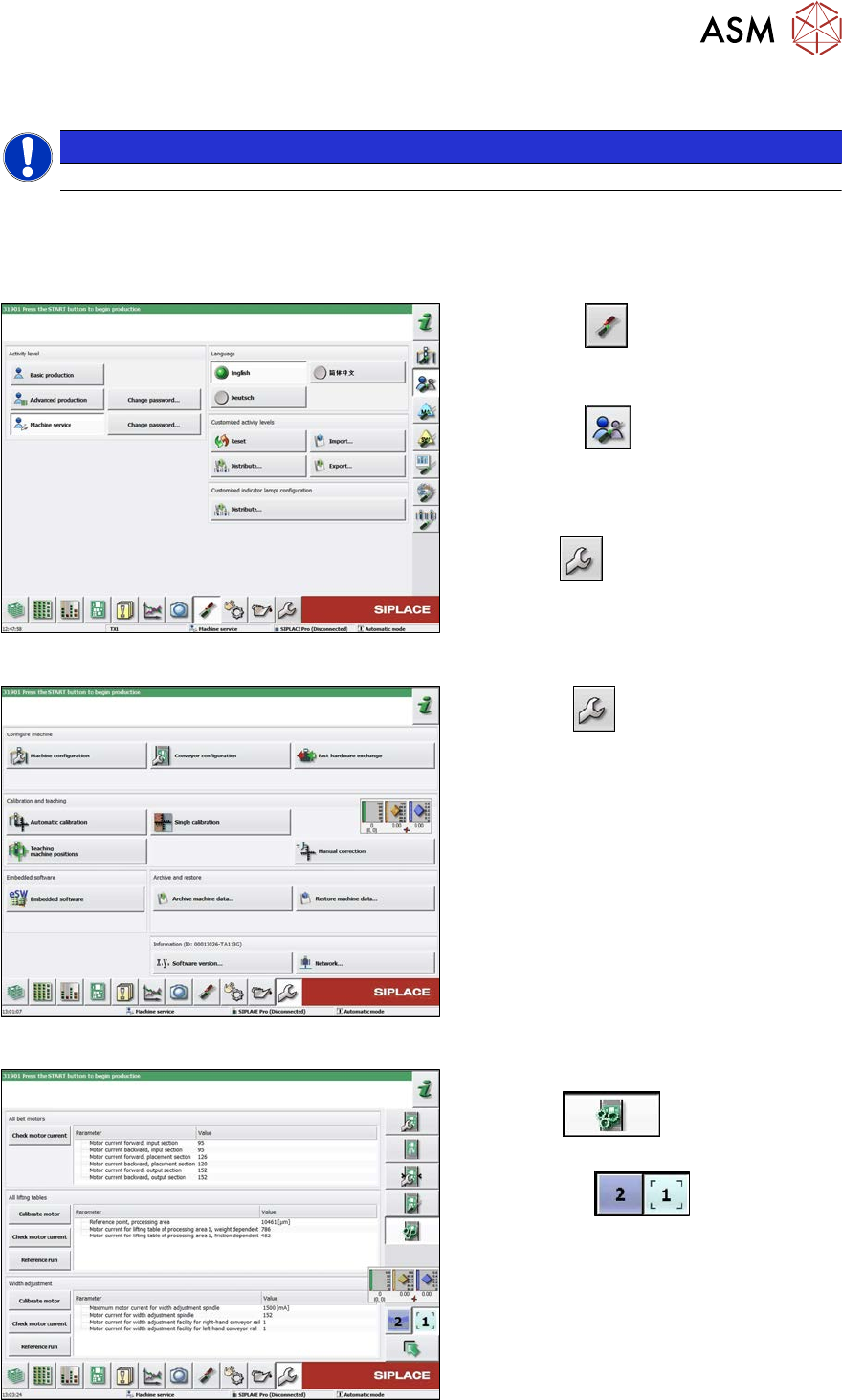
Fig.313: Select operator level
► Select the
button, to open the
Configure, update and calibrate the
machine menu.
► Select the
button to open the
Check and set user settings menu.
► Switch over to the operator level Ma-
chine service.
ð The
button will be shown.
Fig.314: Service menu
► Click the
button to open the Ser-
vice menu.
► Click on the Conveyor Configuration-
button.
Fig.315: Conveyor menu
► Click on the Initiate conveyor para-
meters
button.
► Select the required conveyor track with
the buttons
.
► Go to the section Width adjustment
and select the button Calibrate motor.
7 Conveyor
7.6 Conveyor Belt, Belt Drive and Hexagonal Shaft
246 Service Manual SIPLACE X-Serie S 06/2019
7.6 Conveyor Belt, Belt Drive and Hexagonal Shaft
7.6.1 Replacing the Toothed Belt (Conveyor Belt)
Parts, equipment and tools
●
Toothed belt
Select the relevant toothed belt:
Toothed belt (conveyor) – X series S
Location Standard With I/O extension
Input area Synchronous belt L=753mm
[03094116‑xx]
Synchronous belt L=1239mm
[03093312‑xx]
PA1 Synchronous belt L=1500 mm [03093146-xx]
Center Synchronous belt L=1158 mm [03093314-xx]
PA2 Synchronous belt L=1500 mm [03093146-xx]
Output area Synchronous belt L=753mm
[03094116‑xx]
Synchronous belt L=1239mm
[03093312‑xx]
●
If needed, bearing for hexagonal shaft SXa (plastic bearing) – pack of 10 [03092024-xx]
Removal
► Use the software to move the conveyor sides into a position which allows you best access. As
an alternative, you can loosen the clamps for the relevant sides in dual conveyors.
7.2 "Loosening the Conveyor Side Clamps" [}207]
► Switch off the machine, disconnect it from the power supply and secure it to prevent
unauthorized reactivation.
1.2 "Preparatory work..." [}16]
► Loosen the hexagonal shaft on the belt drive or conveyor drive (motor), so that you can move
the shaft freely. To do this, dismantle the hexagonal shaft fixture on one side and the corres-
ponding plastic bearing on both sides.
7.6.6 "Replacing the hexagonal shaft" [}253]
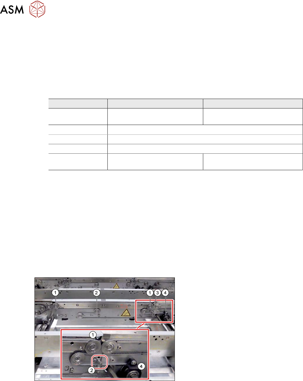
Fig.316: Toothed belt
► Loosen the movable idler pulley (2).
► Loosen the top two idler pulleys(1).
► Remove the screws fastening the belt
drive(4) (or conveyor drive).
► If you replace a conveyor belt in the
placement area, you will also need to
loosen the top retaining screw (3) on
the spring. Make sure that you do not
lose the spring and the bushing on the
screw. When you refit them, check the
bushing for correct orientation.
► Carefully unthread the conveyor belt.