00197042-04_SM_X-Serie-S_Customer_EN.pdf - 第394页
9 Component feeding 9.4 Docking Station for Component Trolley 394 Service Manual SIPLACE X-Serie S 06/2019 9.4.11 Replacing the control valve Parts Fig.536: Control valve 03003489-xx Control valve Equipment and tools 00…
9 Component feeding
9.4 Docking Station for Component Trolley
Service Manual SIPLACE X-Serie S 06/2019 393
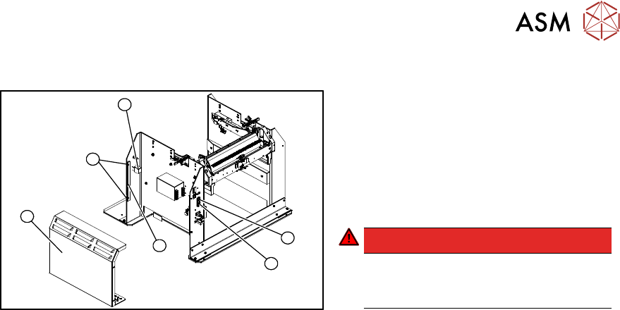
Removal and installation
4
6
5
1
3
2
Fig.535: Removing the unlocking pushbutton
1. ON / OFF switch
2. Power supply plug
3. Cover
4. Bar for clamping the cover
5. Four screws fastening the cover
6. Terminal block for pushbutton
DANGER!
Switch off the voltage supply
Press the ON/OFF button (1) to switch off
and then unplug the power supply (2).
.
► Remove the four screws (5) fastening the cover (3). The cover is clamped in place with the
help of the bar (4).
► Pull the cover (1) out of the docking station.
► Take care not to damage the ground connection.
► Remove the screw fastening the terminal block (6) of the pushbutton.
► Turn the terminal block and extract it from its fixtures.
► Label the connection leads and disconnect these from the terminal block.
► Connect the connection cables to the new pushbutton.
► Fit the new pushbutton.
► Refit the cover.
► Connect the power pack connection cable and press the ON/OFF button to switch on.
► Check the function of the pushbutton by trying out the unlocking procedure.
9 Component feeding
9.4 Docking Station for Component Trolley
394 Service Manual SIPLACE X-Serie S 06/2019
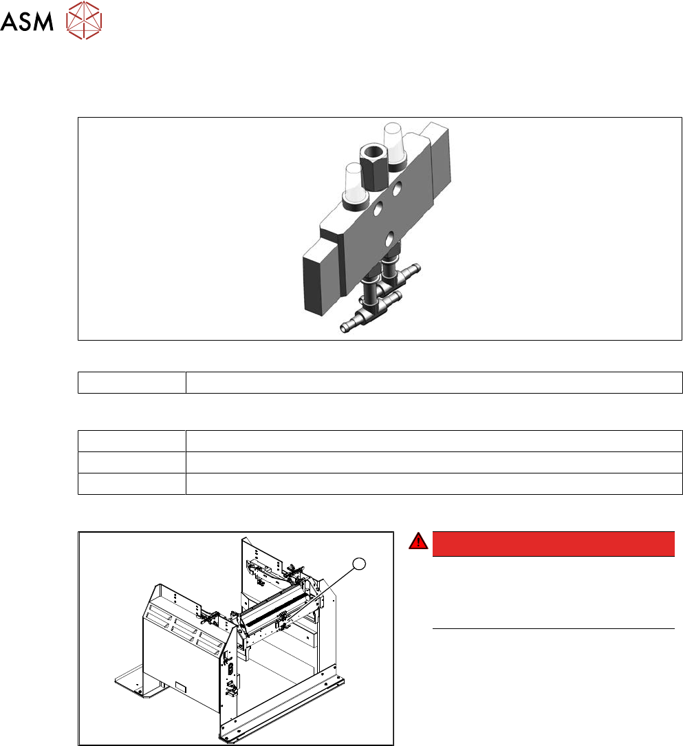
9.4.11 Replacing the control valve
Parts
Fig.536: Control valve
03003489-xx Control valve
Equipment and tools
00353832-xx Allen key set
Wire cutters
Cable ties
Removal / installation
1
Fig.537: Removing the control valve
DANGER!
Switch off the voltage supply
Press the ON/OFF button to switch off
and then unplug the power supply.
Switch off the compressed air supply.
.
► Disconnect the electrical and pneu-
matic connections to the control
valve(1).
► Remove the screws fastening the con-
trol valve and then remove the control
valve.
► Install the new control valve.
► Reconnect to the electrical and com-
pressed air systems.
9 Component feeding
9.5 Manual Table and JEDEC Tray Feeder
Service Manual SIPLACE X-Serie S 06/2019 395
9.5 Manual Table and JEDEC Tray Feeder
NOTICE
See the assembly instructions
For more information about the manual table and the JEDEC tray feeder, read the following
documents:
► Assembly instructions JEDEC Tray Feeder – X-Series S [00197446-xx]
► User manual JEDEC Tray Feeder [00197446-xx]
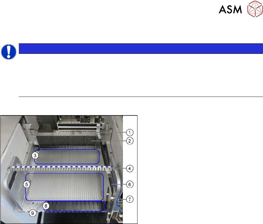
9.5.1 Manual table
Fig.538: Manual table
1. Fixture bar
2. FCU
3. Guide profiles on the front section
4. Fixture bar
5. Guide profiles on the back section
6. Fiducial feeder
7. Pneumatics
8. Feeder infeed
9. Location for the JTF