00197042-04_SM_X-Serie-S_Customer_EN.pdf - 第281页
7 Conveyor 7.8 Laser light barriers, fiber optic cable and PCB sensors Service Manual SIPLACE X-Serie S 06/2019 281 7.8.7 Replacing the Fiber Optic Cable Sensor Parts, equipment and tools ● Fiber optic sensor WLL180T-M p…
7 Conveyor
7.8 Laser light barriers, fiber optic cable and PCB sensors
280 Service Manual SIPLACE X-Serie S 06/2019
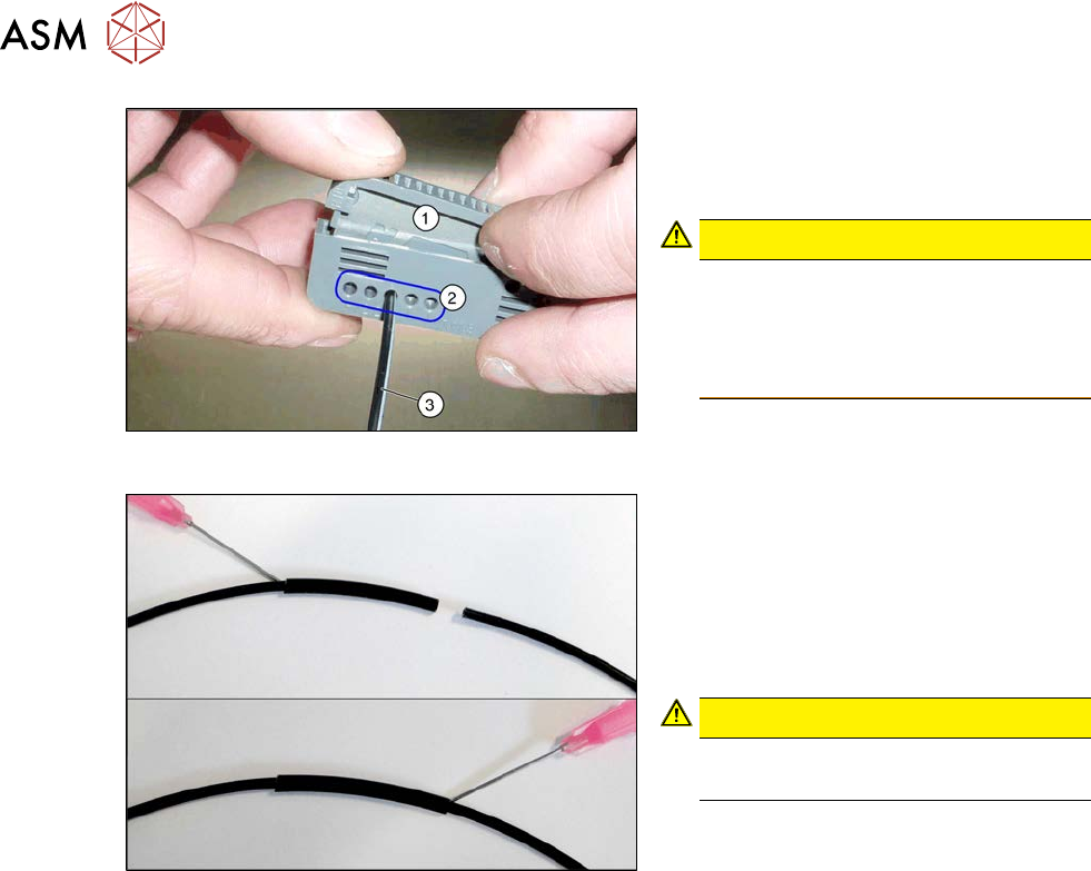
Fig.354: Cutter tool
1. Cutter tool
2. Cutting aperture
3. Fiber optic cable
CAUTION!
Only use each cutting aperture once
Make sure that you only use each cut-
ting aperture once. If they are used
more than once, good quality cuts can
not be guaranteed.
.
Fig.355: Repairing the fiber optic cables
► Slide both ends of the fiber optic cable
into the repair hose until they touch
each other.
► Use Loctite 406 on the repair hose.
Thus, the fiber optic cable is fixed in the
hose. The two ends of the fiber optic
cable are not glued to each other.
CAUTION!
Highly viscous instant glue
Use gloves and a dosage tip.
.
► Further installation is performed by following the above instructions in the reverse order. Also
observe the following instructions:
●
Check the setting for the transmitter/receiver and correct if necessary.
7.8.3 "Checking the laser light barrier" [}270]
7.8.4 "Correcting the Laser Light Barrier Setting" [}273]
●
Calibrate the sensors of the PCB conveyor.
●
Check the display on the fiber optic sensor. The value shown must be over 100. Check the
value for the various conveyor widths (red = output / green = input).
●
Mark the optical system and the fiber optic cable at the fiber optic sensor with the glue dot
supplied. The glue dot indicates that the fiber optic cable has already been repaired and that a
replacement is compulsory at the next defect.
7 Conveyor
7.8 Laser light barriers, fiber optic cable and PCB sensors
Service Manual SIPLACE X-Serie S 06/2019 281
7.8.7 Replacing the Fiber Optic Cable Sensor
Parts, equipment and tools
●
Fiber optic sensor WLL180T-M pre-programmed SXa [03093294-xx] (master) or
Fiber optic sensor WLL180T-F pre-programmed SXa [03093295-xx] (slave)
●
If needed: screwless end stop 6mm 249-116 [00356396‑xx]
Overview
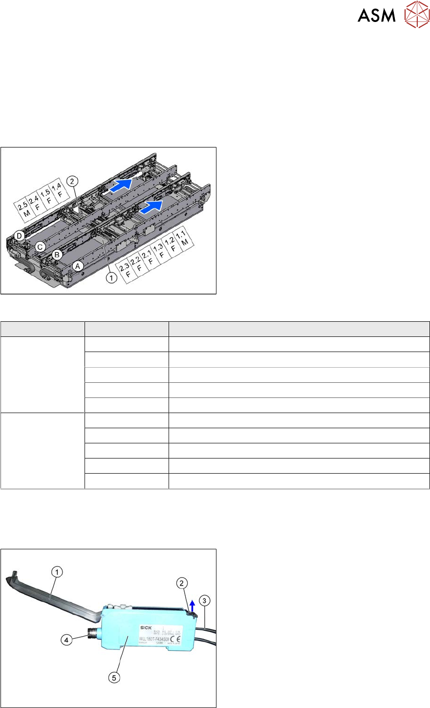
Fig.356: Overview of fiber optic cable sensor
The fiber optic cable sensors are located at
locations 1 and 4, under the covers of the con-
veyor control(1) and(2).
The sensors for the input conveyor, placement
area 1 and intermediate conveyor can be
found at (1).
The sensors for placement area 2 and the out-
put conveyor can be found at (2).
The fiber optic cable sensors are separated
into master (M) and slave (F).
The receiver is always at the top of the
sensors and the transmitter at the bottom.
The transmitters are located on sides B and D.
The receivers are located on sides A and C.
Conveyor lane Designation Location
Lane 1 1.1 Input belt
1.2 Placement area 1
1.3 Intermediate belt
1.4 Placement area 2
1.5 Output belt
Lane 2 2.1 Input belt
2.2 Placement area 1
2.3 Intermediate belt
2.4 Placement area 2
2.5 Output belt
The master synchronizes the slaves to prevent any mutual interference. This is conducted via a side
connection to the neighboring sensor. For this reason, do not simply lift the sensors up and off the strip.
Each sensor has two fiber optic cables connected (transmitter/receiver), which belong to the same
conveyor belt (segment).
Fig.357: Fiber optic cable sensor
1. Cover
2. Locking the fiber optic cables
top = open
bottom = closed
3. Fiber optic cable
4. Electrical connection
5. Electrical connection to neighboring
receiver (under the plastic cover)
7 Conveyor
7.8 Laser light barriers, fiber optic cable and PCB sensors
282 Service Manual SIPLACE X-Serie S 06/2019
Removal
CAUTION
Do not bend the fiber optic cable
► Make sure you do not bend the fiber optic cable. These will otherwise become cloudy
and no longer transmit the signal properly.
► Use the software to move the conveyor sides into a position which allows you best access. As
an alternative, you can loosen the clamps for the relevant sides in dual conveyors.
7.2 "Loosening the Conveyor Side Clamps" [}207]
► Switch off the machine, disconnect it from the power supply and secure it to prevent
unauthorized reactivation.
1.2 "Preparatory work..." [}16]
► Dismantle the cover on the fiber optic sensors.
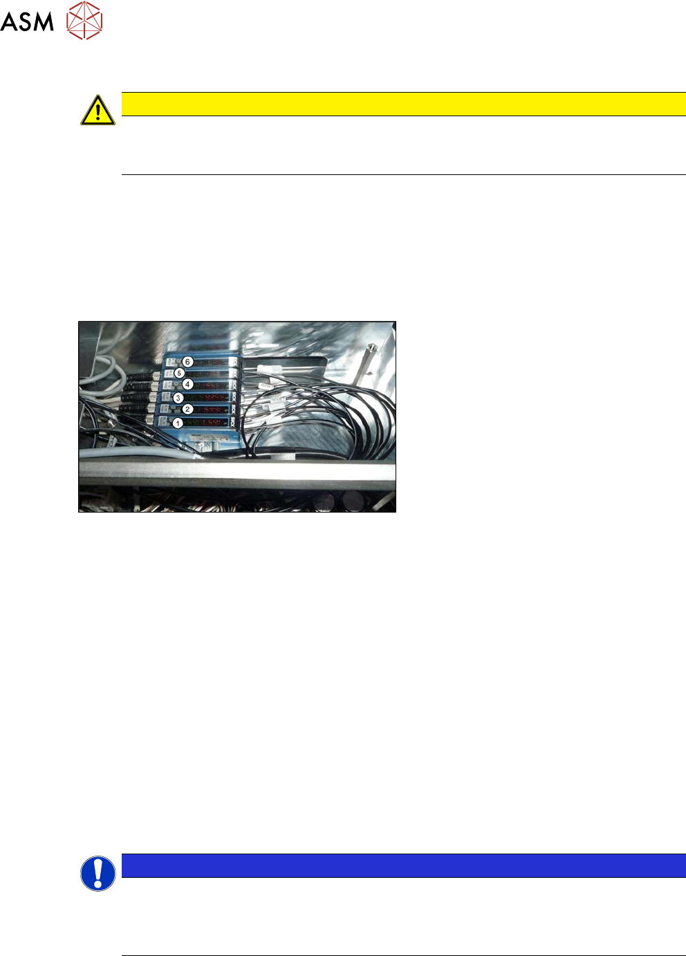
Fig.358: Fiber optic cable sensors
The individual sensors are connected to one
another via a small terminal strip. Dismantle
the sensors one after one, beginning with
(1), until you have reached the sensor to be
replaced. Perform the following tasks at
each sensor:
► Open the cover.
► Open the lock on the fiber optic cables and then unplug the fiber optic cables. You may want
to mark their positions, to make clear assignment easier later on.
► Disconnect from the power supply. You may want to mark the position of this connection to
make clear assignment easier later on.
► Pull the sensor slightly away from the other sensors. Now you can pull the sensor up and off
the strip.
► Repeat these steps if needed for any other sensors.
Installation
Installation is performed by following the above instructions in the reverse order. Also observe the
following instructions:
► Check the setting on the fiber optic sensor and correct if necessary. (See 7.8.8 "Setting the
fiber optic sensor" [}283])
New sensors are preset.
► Remove the plastic cover for the sensor on the side press-fit connections, if needed.
NOTICE
End stops
The fiber optic cable sensors are held at both ends by end stops. If these end stops are
missing or are defective, this can lead to loose connections.
► Replace the end stops when needed.
► Teach the PCB sensors.