00197042-04_SM_X-Serie-S_Customer_EN.pdf - 第199页
6 Gantries 6.7 Filter and pneumatics Service Manual SIPLACE X-Serie S 06/2019 199 ► Mark all pneumatic connections to the vacuum distributor, to make clear assignment easier later on. ► Unplug all pneumatic connections t…
6 Gantries
6.7 Filter and pneumatics
198 Service Manual SIPLACE X-Serie S 06/2019
6.7 Filter and pneumatics
6.7.1 Replacing the vacuum distributor on the placement head
Parts, equipment and tools
●
Distributor placement head vacuum [03029190-xx]
CAUTION
Use the correct blanking plugs
► Only use blanking plugs in the machine which match the manufacturer's compressed
air connection. A tight fit cannot be guaranteed for other blanking plugs.
► We recommend the use of blanking plugs made by Festo.
Overview
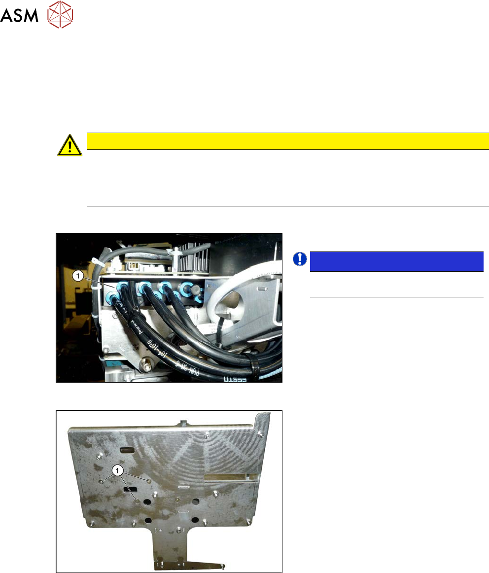
Fig.251: Overview of vacuum distributor
1. Vacuum distributor
NOTICE!
There may still be a pressure sensor
on the vacuum distributor.
.
See 6.7.2 "Replacing the pressure
sensor" [}199].
Fig.252: Screws fastening the vacuum distributor
1. Screws fastening the vacuum distrib-
utor
The screws fastening the vacuum distributor
are located under the head interface.
Removal
► Switch off the machine, disconnect it from the power supply and secure it to prevent
unauthorized reactivation.
1.2 "Preparatory work..." [}16]
► Switch off the compressed air supply
5.2 "Disabling the compressed air supply" [}134]
► Dismantle the Vision board spread spectrum (see 6.4.7 "Replacing the Vision board spread
spectrum HCU" [}178]).
► Dismantle the head interface (see 6.4.5 "Replacing the Head Interface" [}172]).
6 Gantries
6.7 Filter and pneumatics
Service Manual SIPLACE X-Serie S 06/2019 199
► Mark all pneumatic connections to the vacuum distributor, to make clear assignment easier
later on.
► Unplug all pneumatic connections to the vacuum distributor.
► Remove the screws fastening the vacuum distributor and then remove the vacuum distributor.
Installation
► Follow the removal instructions in reverse order for installation.
6.7.2 Replacing the pressure sensor
Parts, equipment and tools
●
Upgrade kit - pressure sensor for vacuum SIPLACE C&P20P [03108457‑xx]
Overview
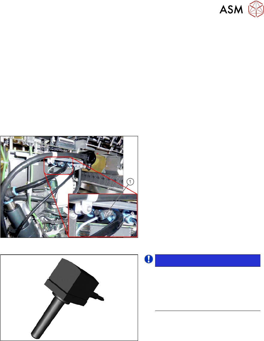
Fig.253: Pressure sensor on the gantry
1. Pressure sensor
The pressure sensor is located on the
vacuum distributor of the gantry and is con-
nected to the head interface (X8) adapter.
Fig.254: Pressure sensor
NOTICE!
The pressure sensor is only needed
when a vacuum pump and CPx heads
are installed.
In this case, the pressure sensor is es-
sential for operation of the placement
machine.
.
Removal
► Switch off the machine, disconnect it from the power supply and secure it to prevent
unauthorized reactivation.
1.2 "Preparatory work..." [}16]
► Switch off the compressed air supply
5.2 "Disabling the compressed air supply" [}134]
► Unplug the electrical connection of the pressure sensor to the head interface (X8).
► Disconnect the pressure sensor from the vacuum distributor on the gantry.
Installation
► Follow the removal instructions in reverse order for installation.
6 Gantries
6.8 Sensor, motor and guide trolley
200 Service Manual SIPLACE X-Serie S 06/2019
6.8 Sensor, motor and guide trolley
6.8.1 Replacing the head plate sensors (temperature sensor)
Parts, equipment and tools
●
Gantry sensor module HCU [03071974-xx]
●
Gap fillers, where required / GTQ2100 d:4.6mm 7x16mm [03014285‑xx]
Overview
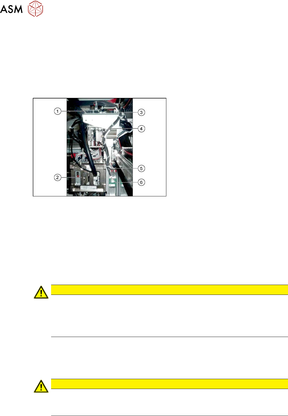
Fig.255: Overview of temperature sensor
1. Vision board
2. Placement head on gantry
3. Head interface
4. Cable from temperature sensor and in-
cremental encoder X axis to head inter-
face
5. The X axis incremental encoder
6. Temperature sensor
Removal
► Switch off the machine, disconnect it from the power supply and secure it to prevent
unauthorized reactivation.
1.2 "Preparatory work..." [}16]
► You can also dismantle the pin picker, if present, for better access.
9.6.1 "Replacing the Pin Picker Assembly" [}399]
► Unplug the cable from the head interface, unthread it and loosen all cable ties.
► Remove the two screws fastening the board and then pull it off.
CAUTION
Rubber foam
Under this board there is heat-conductive rubber foam (gap filler) or heat-conductive paste.
► Do not remove the heat-conductive rubber foam.
► The heat-conductive paste needs to be replaced during refitting. You may need to
remove the old heat-conductive paste, if it is still present.
Installation
► Fix the board into place with the two fastening screws.
► Insert the cable, thread through to the head interface and then connect. Replace any opened
cable ties.
CAUTION
Check how the cables are run!
► Make sure that the end stops (red buffers) do not rub against the cable of the board.
► Make sure that the cable for the board can not collide with the X axis end stopper.