00197042-04_SM_X-Serie-S_Customer_EN.pdf - 第365页
9 Component feeding 9.2 COT insert Service Manual SIPLACE X-Serie S 06/2019 365 9.2.7 Replacing the safety switch Parts, equipment and tools ● Safety switch [03019065-xx] Overview 3 2 1 Fig.490: Safety switch 1. Safety …
9 Component feeding
9.2 COT insert
364 Service Manual SIPLACE X-Serie S 06/2019
Removal
► Dismantle the feeder unlock device. (See 9.2.5 "Replacing the 40-fold feeder unlock
device" [}362])
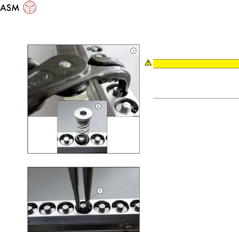
Fig.488: Circlip
► Use the inside circlip pliers to remove
the circlip.
CAUTION!
Spring
Under the circlip you will find a spring
(2). Make sure that the circlip and the
upper guidance bushing do not blow
away and get lost.
.
Fig.489: Snipe pliers
► Use the snipe pliers to remove the un-
locking pin.
Installation
► Follow the removal instructions in reverse order for installation.
9 Component feeding
9.2 COT insert
Service Manual SIPLACE X-Serie S 06/2019 365
9.2.7 Replacing the safety switch
Parts, equipment and tools
●
Safety switch [03019065-xx]
Overview
3
2
1
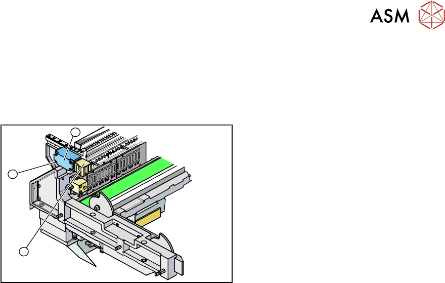
Fig.490: Safety switch
1. Safety switch
2. Four fastening screws
3. Contact jack
Removal
► Switch off the machine, disconnect it from the power supply and secure it to prevent
unauthorized reactivation.
1.2 "Preparatory work..." [}16]
► Depending on the options installed, you may need to loosen the COT insert and pull it slightly
forwards for better access. For more information about this, read section 9.2.3 "Replacing the
COT Insert Assembly" [}356].
► Dismantle the nozzle changer for better access.
► Remove the screws fastening the safety switch.
► Unthread the connection cable up to the connectors down in the machine frame and to the
feed control and then unplug it. Dismantle the two cover plates at the back of the COT insert.
Installation
► Installation is performed by following the above instructions in the reverse order. Also observe
the following instructions:
– Move the component trolley into the COT insert and check whether the component trolley
can be moved into the contact jack. Correct the position of the safety switch, where neces-
sary.
9 Component feeding
9.2 COT insert
366 Service Manual SIPLACE X-Serie S 06/2019
9.2.8 Replacing the empty tape duct assembly
NOTICE
Manual and changeover table
The work described in this chapter applies both to the manual table and the changeover
table. Any relevant differences will be mentioned explicitly.
Parts, equipment and tools
●
COT insert:
– SIPLACE SX4, DX4, X2 S, X3 S, X3 S, X4 S: empty-tape duct assembly [03052576-xx]
– SIPLACE X4i S: Completing replacing the empty-tape duct (LLK ASP) speed flex
[03089515-xx]
●
Manual table:
– SIPLACE X-Series S location 2: empty-tape duct assembly M2 [03103926-xx]
– SIPLACE X-Series S location 3: empty-tape duct assembly M3 [03104547-xx]
Overview
4
1
4
3
2
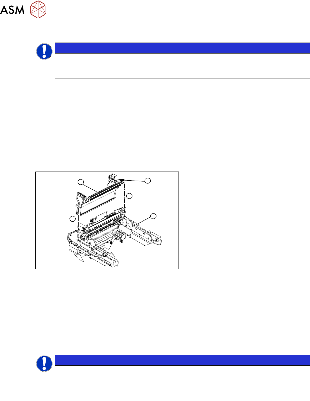
Fig.491: COT insert
1. COT insert assembly
2. Empty tape duct assembly
3. Position of the sensors
Removal
► Switch off the machine, disconnect it from the power supply and secure it to prevent
unauthorized reactivation.
1.2 "Preparatory work..." [}16]
► Mark the position of the sensors (reed contacts) and remove these from the reject container.
► Dismantle the nozzle changer, if required.
2.8.2 "Replacing the Nozzle Changer" [}44]
NOTICE
Manual table
If you are working on a manual table, you will need to also perform the following tasks be-
fore dismantling the feeder unlock device and the FCU:
► Dismantle the back and front section of the manual table.
► Dismantle the feeder unlock device 40/2-fold (see 9.2.5 "Replacing the 40-fold feeder unlock
device" [}362]).
► Dismantle the FCU.
9.2.4 "Replacing the Feeder Control Unit (FCU)" [}358]
► Remove the two screws (4) holding the empty tape duct (2). Depending on the version of your
COT insert, you may need to first dismantle the safety switch and the COT insert control, oth-
erwise the screws will not be accessible.