00197042-04_SM_X-Serie-S_Customer_EN.pdf - 第272页
7 Conveyor 7.8 Laser light barriers, fiber optic cable and PCB sensors 272 Service Manual SIPLACE X-Serie S 06/2019 Fig.346: Sensors ► Enable the Laser light barrier button. ► Click on the button Check sensors and funct…
7 Conveyor
7.8 Laser light barriers, fiber optic cable and PCB sensors
Service Manual SIPLACE X-Serie S 06/2019 271
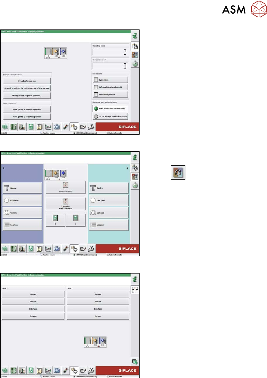
Fig.343: Safety mode
► Enable the button Safety mode (re-
duced speed).
Fig.344: Check sensors and functions
► Click on the button Check sensors
and functions of specific compon-
ents
.
► Click on the Conveyor inputs/outputs
button.
Fig.345: Inputs/outputs
► Click on the button Sensors.
7 Conveyor
7.8 Laser light barriers, fiber optic cable and PCB sensors
272 Service Manual SIPLACE X-Serie S 06/2019
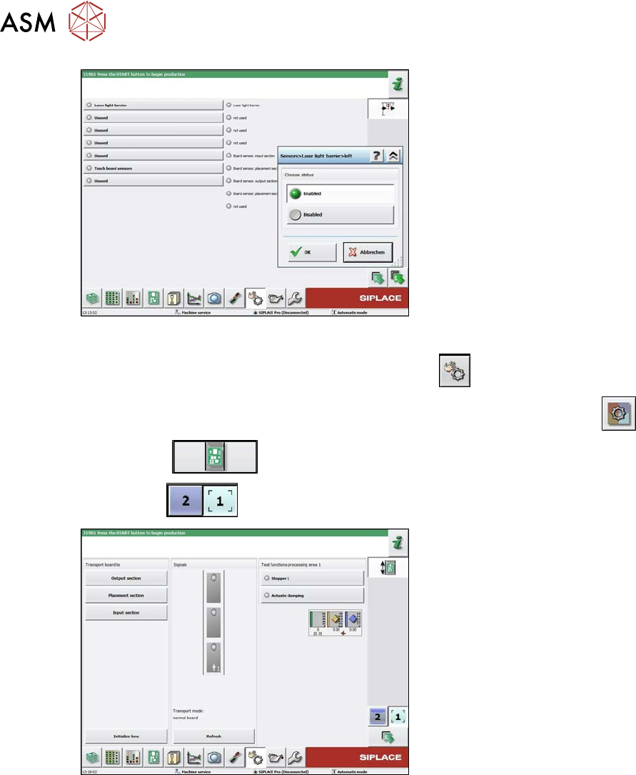
Fig.346: Sensors
► Enable the Laser light barrier button.
► Click on the button Check sensors and functions
.
► Click on the button Check sensors and functions of specific components
.
► Click the
button.
► Use the
button to select the required conveyor track.
Fig.347: Checking function of the laser light
► Check the function of the laser light
barrier. To do this, move a board
through the conveyor.
► Correct the laser light barrier setting, if
necessary (see below).
7 Conveyor
7.8 Laser light barriers, fiber optic cable and PCB sensors
Service Manual SIPLACE X-Serie S 06/2019 273
7.8.4 Correcting the Laser Light Barrier Setting
DANGER
Laser class 2
The laser light barrier transmitter emits class 2 laser beams. You therefore do not require
additional protective measures!
► However, you should never look into the laser beam!
► Adjust the laser beam only from the rear side of the laser!
Parts, equipment and tools
●
Recommendation for new version of receiver (silver receiver surface):
semi-transparent paper or plastic (for better recognition of laser beam)
Overview
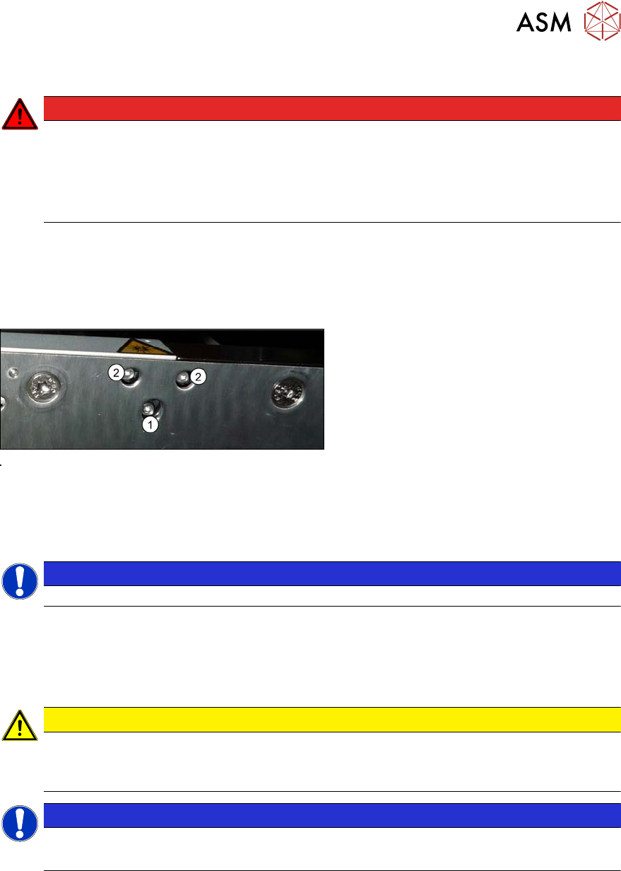
Fig.348: Laser light barrier
1. Fastening screw
2. Setting screws
Procedure
► Set the maximum conveyor width.
NOTICE
Deviation of the laser beam has the greatest effect at maximum conveyor width.
► Select "Enable safety mode".
► Activate the relevant laser diode using the input/output functions in the station software.
► Use the top two screws to set the laser beam so that it is correctly aligned with the laser recei-
ver.
CAUTION
Screws on the laser transmitter
► Hand-tighten the lower screw. The top two screws are used to set the laser beam.
These may not be fully tightened, otherwise the laser transmitter could be damaged.
NOTICE
Semi-transparent paper or plastic
► Use semi-transparent paper or plastic to make the laser beam visible on the receiver.
► Now position the conveyor to minimum width and check the setting,
► Check the PCB reference corner and reteach, if necessary.