00197042-04_SM_X-Serie-S_Customer_EN.pdf - 第402页
9 Component feeding 9.6 Smart Pin Support 402 Service Manual SIPLACE X-Serie S 06/2019 9.6.3 Replacing the back section of the cylinder CAUTION Do not change! The back section of the cylinder is preset with a cover strip…
9 Component feeding
9.6 Smart Pin Support
Service Manual SIPLACE X-Serie S 06/2019 401
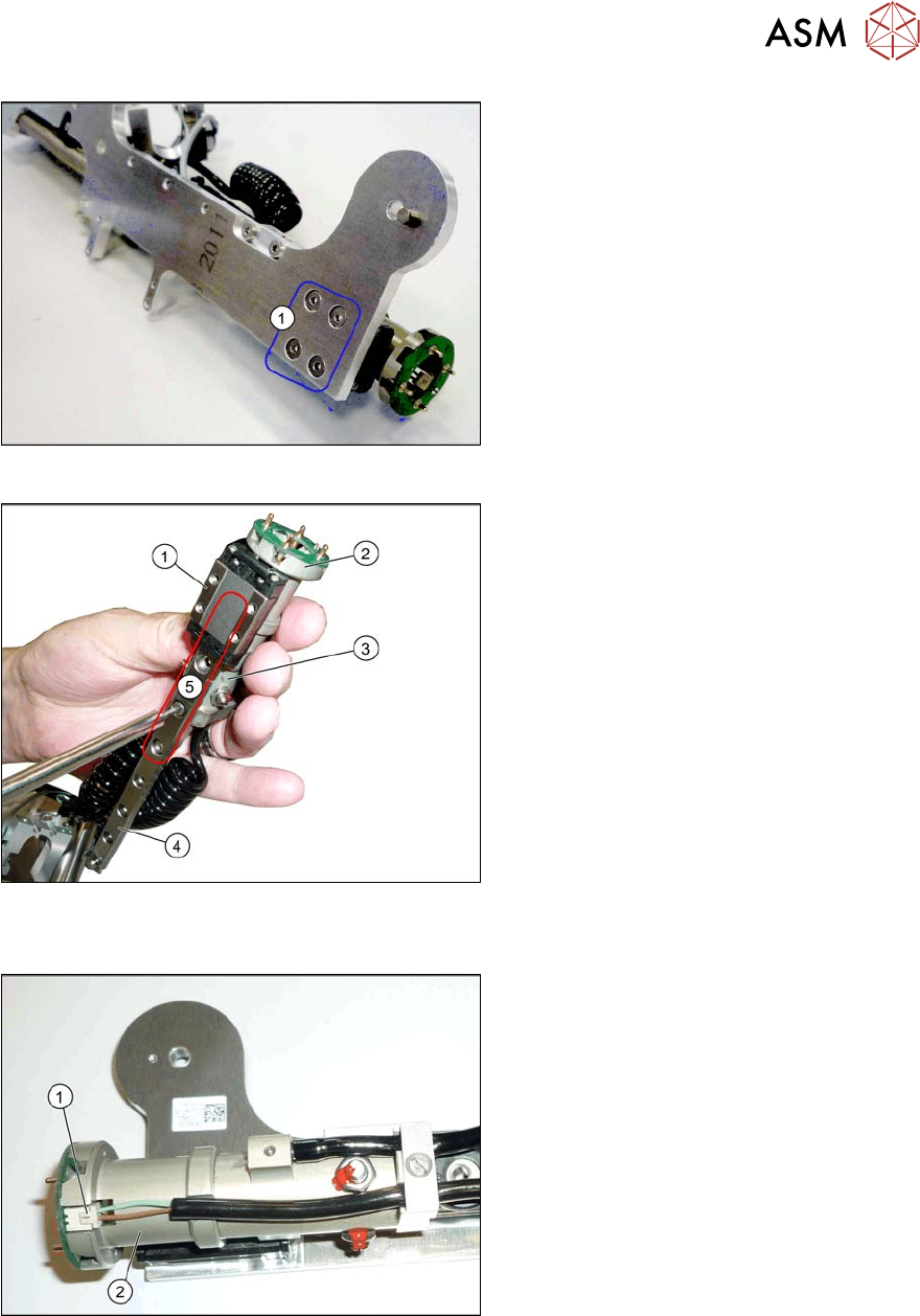
Fig.548: Screws fastening the linear guide
► Remove the fourscrews(1) fastening
the linear guide.
► Remove the linear guide from the base
plate. To do this, unhook the spring
from the top of the linear guide.
Fig.549: Screws fastening the cylinder
1. Trolley on the linear guide
2. Cylinder - front section
3. Cylinder - back section
4. Linear guide
5. Fastening screw for cylinder front and
back sections on the linear guide (par-
tially concealed by the trolley)
► Remove the fastening screws on the front and back sections of the cylinder.
Fig.550: Connector
► Unplug the electrical connection(1) to
the front section of the cylinder(2).
► Remove the front section of the cylin-
der.
Installation
► Follow the removal instructions in reverse order for installation. Also observe the following
instructions:
– When you screw in the linear guide carriage, press it to the left, against the stop edge, so
that it lies flush against the base plate.
9 Component feeding
9.6 Smart Pin Support
402 Service Manual SIPLACE X-Serie S 06/2019
9.6.3 Replacing the back section of the cylinder
CAUTION
Do not change!
The back section of the cylinder is preset with a cover strip take-up force of 12N+/‑2N for
the pin picker and may not be changed.
Parts, equipment and tools
●
Cylinder back section assembly [03089379Sxx]
●
Assembly instructions "Smart Pin Support" for SIPLACE X‑SeriesS [DEEN:00197394‑xx]
Overview
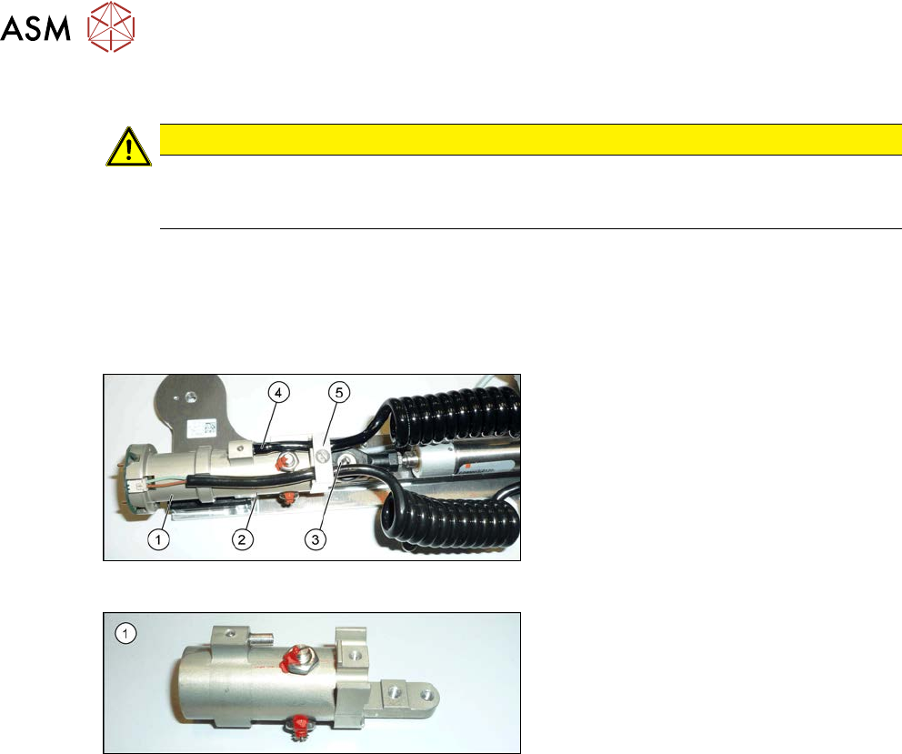
Fig.551: Cylinder
1. Cylinder - front section
2. Cylinder - back section
3. Swivel head
4. Pneumatic connection to the back sec-
tion of the cylinder
5. Tension relief
Fig.552: Cylinder - back section
1. Cylinder - back section
Removal
► Switch off the machine, disconnect it from the power supply and secure it to prevent
unauthorized reactivation.
1.2 "Preparatory work..." [}16]
► Remove the pin picker. For more information, read section 9.6.1 "Replacing the Pin Picker
Assembly" [}399].
► Remove the front section of the cylinder. For more information, read section 9.6.2 "Replacing
the front section of the cylinder" [}400].
► Remove the screw fastening the strain relief.
► Unplug the pneumatic connection to the back section of the cylinder.
► If you have not already done so, undo the two screws fastening the back section of the cylin-
der to the linear guide and then remove the back section of the cylinder.
Installation
► Follow the removal instructions in reverse order for installation. Also observe the following
instructions:
– When you screw in the linear guide carriage, press it to the left, against the stop edge, so
that it lies flush against the base plate.
– Make sure that the coil hose and the coiled cable do not touch when fully extended.
– Check that the sensors switch properly. The switch tag of the linear guide must have ap-
prox. 1 mm space to the trolley.
9 Component feeding
9.6 Smart Pin Support
Service Manual SIPLACE X-Serie S 06/2019 403
9.6.4 Replacing the linear guide
Parts, equipment and tools
●
SPS linear guide [03084323Sxx]
●
Assembly instructions "Smart Pin Support" for SIPLACE X‑SeriesS [DEEN:00197394‑xx]
Overview
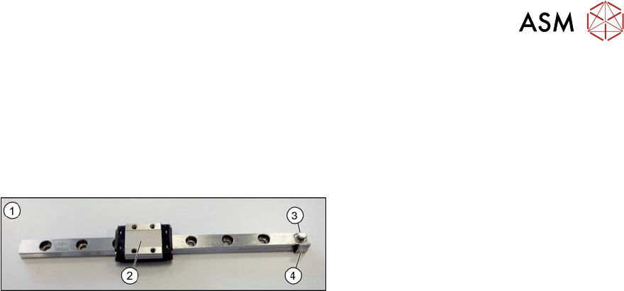
Fig.553: Linear guide
1. Linear guide
2. Trolley
3. Eyelet for hooking up the tension spring
4. Switch tag
Removal
► Switch off the machine, disconnect it from the power supply and secure it to prevent
unauthorized reactivation.
1.2 "Preparatory work..." [}16]
► Remove the pin picker. For more information, read section 9.6.1 "Replacing the Pin Picker
Assembly" [}399].
► Remove the front section of the cylinder. For more information, read section 9.6.2 "Replacing
the front section of the cylinder" [}400].
► Remove the back section of the cylinder. For more information, read section 9.6.3 "Replacing
the back section of the cylinder" [}402].
► Remove the linear guide.
Installation
► Follow the removal instructions in reverse order for installation. Also observe the following
instructions:
– When you screw in the linear guide carriage, press it to the left, against the stop edge, so
that it lies flush against the base plate.
– Check the linear guide travel path. The linear guide must be easy to move along the whole
length.
– Check that the sensors switch properly. The switch tag of the linear guide must have ap-
prox. 1 mm space to the trolley.