SG_FSE_SiplaceHF_HF3_00193900-05_de.pdf - 第114页
1 - 2 S tudent Guide SIPLACE HF/HF3 Inhalt Ausgabe 09/2005 2 4.3.3.3 Einschaltsequenz der Pneumatikeinheiten . . . . . . . . . . . . . . . . . . . . . . . . . . . . . 39 4.3.3.4 Ha uptventil X59 für Maschin enkomponen te…

Student Guide SIPLACE HF/HF3
Ausgabe 09/2005 Inhalt
1
Kapitel
Inhaltsverzeichnis
4 Energieversorgung an der Maschine . . . . . . . . . . . . . . . . . . . . . . . . . . . . . . . . . . . 3
4.1 Überblick. . . . . . . . . . . . . . . . . . . . . . . . . . . . . . . . . . . . . . . . . . . . . . . . . . . . . . . . . . . . . . . . . . . . . . . 3
4.1.1 Überblick Stromversorgung . . . . . . . . . . . . . . . . . . . . . . . . . . . . . . . . . . . . . . . . . . . . . . 4
4.2 Stromversorgung. . . . . . . . . . . . . . . . . . . . . . . . . . . . . . . . . . . . . . . . . . . . . . . . . . . . . . . . . . . . . . . . 7
4.2.1 Festgelegte Bezeichnungen für Anschlüsse und Kabel. . . . . . . . . . . . . . . . . . . . . . . . . 7
4.2.2 Hauptverteiler, Sektor 2 . . . . . . . . . . . . . . . . . . . . . . . . . . . . . . . . . . . . . . . . . . . . . . . . . 8
4.2.3 Zwischenverteiler, Sektor 4 . . . . . . . . . . . . . . . . . . . . . . . . . . . . . . . . . . . . . . . . . . . . . . 9
4.2.4 Stromversorgung . . . . . . . . . . . . . . . . . . . . . . . . . . . . . . . . . . . . . . . . . . . . . . . . . . . . . 10
4.2.4.1 Eingangsspannung. . . . . . . . . . . . . . . . . . . . . . . . . . . . . . . . . . . . . . . . . . . . . . . 13
4.2.4.2 Transformator 1 . . . . . . . . . . . . . . . . . . . . . . . . . . . . . . . . . . . . . . . . . . . . . . . . . 14
4.2.4.3 Transformator 2 . . . . . . . . . . . . . . . . . . . . . . . . . . . . . . . . . . . . . . . . . . . . . . . . . 15
4.2.4.4 Spannungen in der Stromversorgung nach dem Einschalten . . . . . . . . . . . . . . 16
4.2.4.5 DC/DC Wandler (Gleichspannungswandler) in der Hauptstromversorgung . . . 17
4.2.5 Stromversorgung Computereinschub. . . . . . . . . . . . . . . . . . . . . . . . . . . . . . . . . . . . . . 18
4.2.6 Stromversorgung Achseinschub. . . . . . . . . . . . . . . . . . . . . . . . . . . . . . . . . . . . . . . . . . 19
4.2.7 Gleichspannungswandler Vision Sektor 2 . . . . . . . . . . . . . . . . . . . . . . . . . . . . . . . . . . 20
4.2.7.1 Spannungsversorgung Gurtschneider . . . . . . . . . . . . . . . . . . . . . . . . . . . . . . . . 20
4.2.8 Sicherheits und Meldekreis (HF/HF3 bis MA.Nr. xx) . . . . . . . . . . . . . . . . . . . . . . . . . . 21
4.2.8.1 NOT-AUS-Kreis (Sicherheitskreis). . . . . . . . . . . . . . . . . . . . . . . . . . . . . . . . . . . 21
4.2.8.2 Meldekreise . . . . . . . . . . . . . . . . . . . . . . . . . . . . . . . . . . . . . . . . . . . . . . . . . . . . 22
4.2.8.3 Wie funktioniert der NOT-AUS-Kreis? . . . . . . . . . . . . . . . . . . . . . . . . . . . . . . . . 24
4.2.9 Die Sicherheits-Kombination (Relais K6) . . . . . . . . . . . . . . . . . . . . . . . . . . . . . . . . . . . 25
4.2.9.1 Arbeitweise der Schützsicherheitskombination (SSK) . . . . . . . . . . . . . . . . . . . . 27
4.2.10 Verschiedene Signale. . . . . . . . . . . . . . . . . . . . . . . . . . . . . . . . . . . . . . . . . . . . . . . . . 27
4.2.10.1 Software-Freigabe . . . . . . . . . . . . . . . . . . . . . . . . . . . . . . . . . . . . . . . . . . . . . . 27
4.2.10.2 OK-Meldung Sicherheitskreis. . . . . . . . . . . . . . . . . . . . . . . . . . . . . . . . . . . . . . 28
4.2.10.3 Meldung Steuerung EIN. . . . . . . . . . . . . . . . . . . . . . . . . . . . . . . . . . . . . . . . . . 29
4.2.11 Spannungsverteilung . . . . . . . . . . . . . . . . . . . . . . . . . . . . . . . . . . . . . . . . . . . . . . . . . 30
4.3 Pneumatiksystem . . . . . . . . . . . . . . . . . . . . . . . . . . . . . . . . . . . . . . . . . . . . . . . . . . . . . . . . . . . . . . 33
4.3.1 Allgemeines . . . . . . . . . . . . . . . . . . . . . . . . . . . . . . . . . . . . . . . . . . . . . . . . . . . . . . . . . 33
4.3.2 HF Pneumatiksystem . . . . . . . . . . . . . . . . . . . . . . . . . . . . . . . . . . . . . . . . . . . . . . . . . . 34
4.3.3 Pneumatikeinheit . . . . . . . . . . . . . . . . . . . . . . . . . . . . . . . . . . . . . . . . . . . . . . . . . . . . . 35
4.3.3.1 Manometeranordnung . . . . . . . . . . . . . . . . . . . . . . . . . . . . . . . . . . . . . . . . . . . . 36
4.3.3.2 Druckluftverteilung in der Pneumatikeinheit. . . . . . . . . . . . . . . . . . . . . . . . . . . . 37

1 - 2
Student Guide SIPLACE HF/HF3
Inhalt Ausgabe 09/2005
2
4.3.3.3 Einschaltsequenz der Pneumatikeinheiten. . . . . . . . . . . . . . . . . . . . . . . . . . . . . 39
4.3.3.4 Hauptventil X59 für Maschinenkomponenten. . . . . . . . . . . . . . . . . . . . . . . . . . . 40
4.3.3.5 Proportionalventil, Proportionalregler X58 . . . . . . . . . . . . . . . . . . . . . . . . . . . . . 41
4.3.3.6 Sicherheitsventil X60 . . . . . . . . . . . . . . . . . . . . . . . . . . . . . . . . . . . . . . . . . . . . . 42
4.3.3.7 Kühlung der Motoren der Y-Achse im Bestückbereich 1/2. . . . . . . . . . . . . . . . . 43
4.3.3.8 Kühlung der Motoren der X-Achsen . . . . . . . . . . . . . . . . . . . . . . . . . . . . . . . . . . 44
4.3.4 Druckluftversorgung Gurtschneider . . . . . . . . . . . . . . . . . . . . . . . . . . . . . . . . . . . . . . . 44
4.3.5 Druckluftversorgung Andockeinheit (BE-Tisch) . . . . . . . . . . . . . . . . . . . . . . . . . . . . . . 45
4.3.6 Bulk Case-System . . . . . . . . . . . . . . . . . . . . . . . . . . . . . . . . . . . . . . . . . . . . . . . . . . . . 45
4.3.7 Druckluftversorgung Collect & Place-Kopf . . . . . . . . . . . . . . . . . . . . . . . . . . . . . . . . . . 46
4.3.8 Druckluftversorgung Twin Kopf. . . . . . . . . . . . . . . . . . . . . . . . . . . . . . . . . . . . . . . . . . . 47
4.3.8.1 Druckluftverteilung Twin Kopf. . . . . . . . . . . . . . . . . . . . . . . . . . . . . . . . . . . . . . . 48
4.3.8.2 Vakuum und Blasluft am Twin Kopf . . . . . . . . . . . . . . . . . . . . . . . . . . . . . . . . . . 49
4.3.8.3 Sicherheitsmodus Z-Achse. . . . . . . . . . . . . . . . . . . . . . . . . . . . . . . . . . . . . . . . . 50
1 - 3
Student Guide SIPLACE HF/HF3
Ausgabe 09/2005 4 Energieversorgung an der Maschine
3
4 Energieversorgung an der Maschine
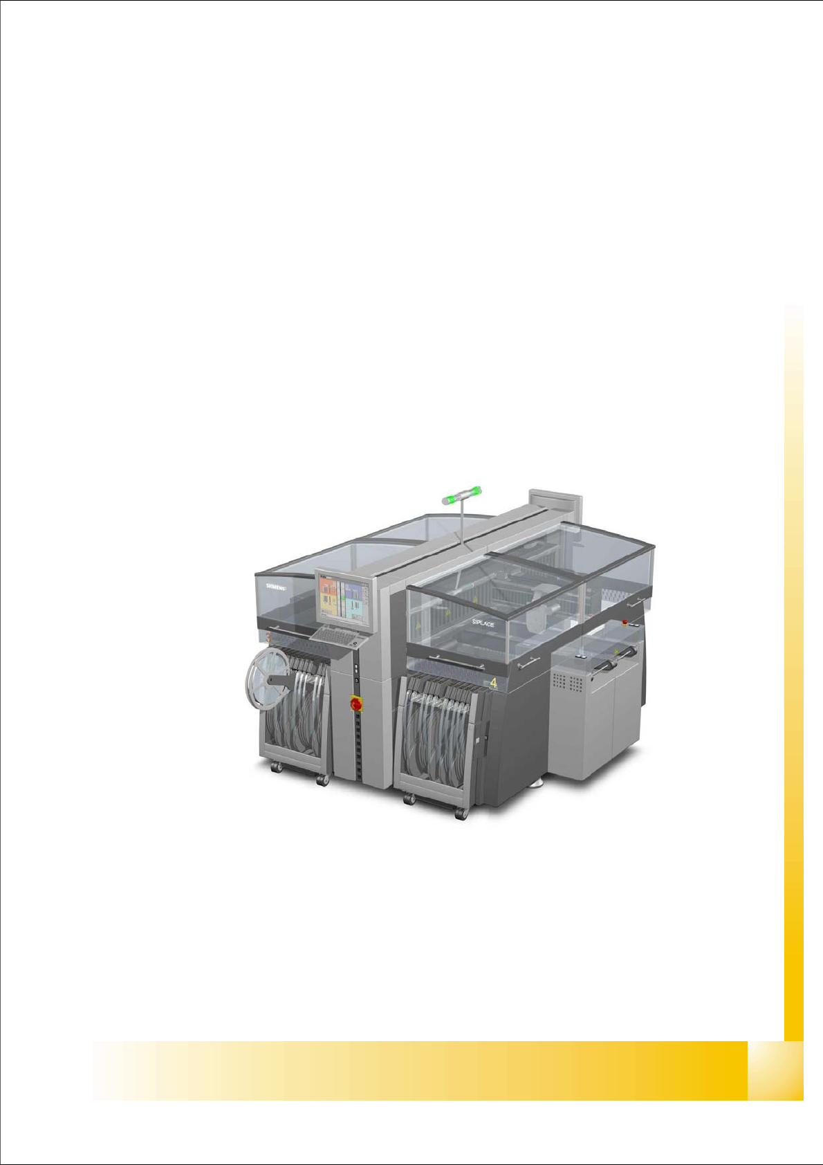
4.1 Überblick
Die Abbildung unten zeigt, wo die zum Betrieb des Systems erforderlichen, energieliefernden und
-verteilenden Komponenten untergebracht sind:
– Stromversorgung mit Hauptverteiler (Pos. 1)
– Sektorenverteiler Sektor 2 (Pos. 2)
– Pneumatikeinheit (Pos. 3)
– Sektorverteiler Sektor 4 (Pos. 4)
Abb. 4.1 - 1 Hauptkomponenten der HF/HF3
S
t
r
o
m
v
e
r
s
o
r
g
u
n
g
Sektor 4
Sektor 2
P
n
e
u
ma
t
i
k
-
E
i
n
h
e
i
t
3
1
4
2