SG_FSE_SiplaceHF_HF3_00193900-05_de.pdf - 第26页
1 - 2 S tudent Guide SIPLAC E HF/HF3 Advanced I Inhalt Ausgabe 09/2005 2 2.2.15.1 Schritte beim Abholen und Bestücken von Bauelementen . . . . . . . . . . . . . . . . 35 2.2.15.2 Position und Funktion de r einzelnen St e…

Student Guide SIPLACE HF/HF3 Advanced I
Ausgabe 09/2005 Inhalt
1
Kapitel
Inhaltsverzeichnis
2 Überblick . . . . . . . . . . . . . . . . . . . . . . . . . . . . . . . . . . . . . . . . . . . . . . . . . . . . . . . . . . 3
2.1 Allgemeines . . . . . . . . . . . . . . . . . . . . . . . . . . . . . . . . . . . . . . . . . . . . . . . . . . . . . . . . . . . . . . . . . . . . 3
2.1.1 Spezifikation und Konfiguration Siplace HF . . . . . . . . . . . . . . . . . . . . . . . . . . . . . . . . . . 5
2.2 Übersicht Komponenten. . . . . . . . . . . . . . . . . . . . . . . . . . . . . . . . . . . . . . . . . . . . . . . . . . . . . . . . . . 8
2.2.1 Schalter . . . . . . . . . . . . . . . . . . . . . . . . . . . . . . . . . . . . . . . . . . . . . . . . . . . . . . . . . . . . . 8
2.2.2 Stromversorgung . . . . . . . . . . . . . . . . . . . . . . . . . . . . . . . . . . . . . . . . . . . . . . . . . . . . . 10
2.2.2.1 Übersicht der Spannungen auf der vorderen Anzeige der Stromversorgung. . . 11
2.2.3 Pneumatik-Einheit . . . . . . . . . . . . . . . . . . . . . . . . . . . . . . . . . . . . . . . . . . . . . . . . . . . . 13
2.2.3.1 Pneumatikkreis zur Kühlung des Y - Linearmotors für Bestückbereich 1/2 . . . . 14
2.2.3.2 Pneumatikkreis zum Kühlen des X - Linearmotors für Bestückbereich 1/2 . . . . 14
2.2.3.3 Verteilerblock Druckluft. . . . . . . . . . . . . . . . . . . . . . . . . . . . . . . . . . . . . . . . . . . . 14
2.2.4 Sektoren 1 - 4. . . . . . . . . . . . . . . . . . . . . . . . . . . . . . . . . . . . . . . . . . . . . . . . . . . . . . . . 15
2.2.5 Computer Unit . . . . . . . . . . . . . . . . . . . . . . . . . . . . . . . . . . . . . . . . . . . . . . . . . . . . . . . 16
2.2.6 Axis Unit . . . . . . . . . . . . . . . . . . . . . . . . . . . . . . . . . . . . . . . . . . . . . . . . . . . . . . . . . . . . 17
2.2.7 Axis units HF3 Maschine . . . . . . . . . . . . . . . . . . . . . . . . . . . . . . . . . . . . . . . . . . . . . . . 18
2.2.7.1 Axis unit Bestückbereich 1 HF3 Maschine. . . . . . . . . . . . . . . . . . . . . . . . . . . . . 18
2.2.7.2 Axisunit Placement Area 2 HF3 machine. . . . . . . . . . . . . . . . . . . . . . . . . . . . . . 19
2.2.7.3 Achskarte A363 . . . . . . . . . . . . . . . . . . . . . . . . . . . . . . . . . . . . . . . . . . . . . . . . . 20
2.2.8 Bauelemente Wechseltisch . . . . . . . . . . . . . . . . . . . . . . . . . . . . . . . . . . . . . . . . . . . . . 21
2.2.8.1 Andocken und Abdocken . . . . . . . . . . . . . . . . . . . . . . . . . . . . . . . . . . . . . . . . . . 21
2.2.8.2 Einstellen der Höhe des BE-Tisches . . . . . . . . . . . . . . . . . . . . . . . . . . . . . . . . . 22
2.2.8.3 Überblick Förderer . . . . . . . . . . . . . . . . . . . . . . . . . . . . . . . . . . . . . . . . . . . . . . . 23
2.2.9 Position der Portale . . . . . . . . . . . . . . . . . . . . . . . . . . . . . . . . . . . . . . . . . . . . . . . . . . . 24
2.2.10 Konstruktion X-Achse. . . . . . . . . . . . . . . . . . . . . . . . . . . . . . . . . . . . . . . . . . . . . . . . . 25
2.2.10.1 Technische Daten X-Achse . . . . . . . . . . . . . . . . . . . . . . . . . . . . . . . . . . . . . . . 26
2.2.11 Konstruktion Y-Achse. . . . . . . . . . . . . . . . . . . . . . . . . . . . . . . . . . . . . . . . . . . . . . . . . 26
2.2.12 Kameras. . . . . . . . . . . . . . . . . . . . . . . . . . . . . . . . . . . . . . . . . . . . . . . . . . . . . . . . . . . 27
2.2.12.1 Standardmodul LP-Kamera . . . . . . . . . . . . . . . . . . . . . . . . . . . . . . . . . . . . . . . 28
2.2.12.2 Bauelemente-Kamera 12 Segmente C&P Kopf. . . . . . . . . . . . . . . . . . . . . . . . 29
2.2.12.3 Bauelemente-Kamera 6-Segment-C&P-Kopf. . . . . . . . . . . . . . . . . . . . . . . . . . 30
2.2.12.4 Fine-Pitch-Kamera für Twin Head . . . . . . . . . . . . . . . . . . . . . . . . . . . . . . . . . . 31
2.2.13 Kopfmodularität HF . . . . . . . . . . . . . . . . . . . . . . . . . . . . . . . . . . . . . . . . . . . . . . . . . . 32
2.2.14 Kopfmodularität HF3 . . . . . . . . . . . . . . . . . . . . . . . . . . . . . . . . . . . . . . . . . . . . . . . . . 33
2.2.15 C&P- Kopf des Typs DLM2 mit 12/6 Segmenten . . . . . . . . . . . . . . . . . . . . . . . . . . . . 34

1 - 2
Student Guide SIPLACE HF/HF3 Advanced I
Inhalt Ausgabe 09/2005
2
2.2.15.1 Schritte beim Abholen und Bestücken von Bauelementen. . . . . . . . . . . . . . . . 35
2.2.15.2 Position und Funktion der einzelnen Stern-Stationen (siehe Abb. 2.2 - 24). . . 35
2.2.15.3 Übersicht der Funktionen der Stern-Stationen 1 - 12. . . . . . . . . . . . . . . . . . . . 36
2.2.15.4 Pipettenwechsler für 12-Segment-C&P-Kopf. . . . . . . . . . . . . . . . . . . . . . . . . . 37
2.2.15.5 Pipettenwechsler für 6-Segment-C&P-Kopf. . . . . . . . . . . . . . . . . . . . . . . . . . . 38
2.2.16 Twin Head für hohe Präzision. . . . . . . . . . . . . . . . . . . . . . . . . . . . . . . . . . . . . . . . . . . 39
2.2.16.1 Beschreibung . . . . . . . . . . . . . . . . . . . . . . . . . . . . . . . . . . . . . . . . . . . . . . . . . . 39
2.2.16.2 Pipettenwechsler Twin Head . . . . . . . . . . . . . . . . . . . . . . . . . . . . . . . . . . . . . . 40
2.2.17 Transportsystem. . . . . . . . . . . . . . . . . . . . . . . . . . . . . . . . . . . . . . . . . . . . . . . . . . . . . 41
2.2.17.1 Allgemeines . . . . . . . . . . . . . . . . . . . . . . . . . . . . . . . . . . . . . . . . . . . . . . . . . . . 41
2.2.17.2 Konstruktion Einzeltransport. . . . . . . . . . . . . . . . . . . . . . . . . . . . . . . . . . . . . . . 43
2.2.17.3 Konstruktion Doppeltransport. . . . . . . . . . . . . . . . . . . . . . . . . . . . . . . . . . . . . . 44
1 - 3
Student Guide SIPLACE HF/HF3 Advanced I
Ausgabe 09/2005 2 Überblick
3
2 Überblick
2.1 Allgemeines
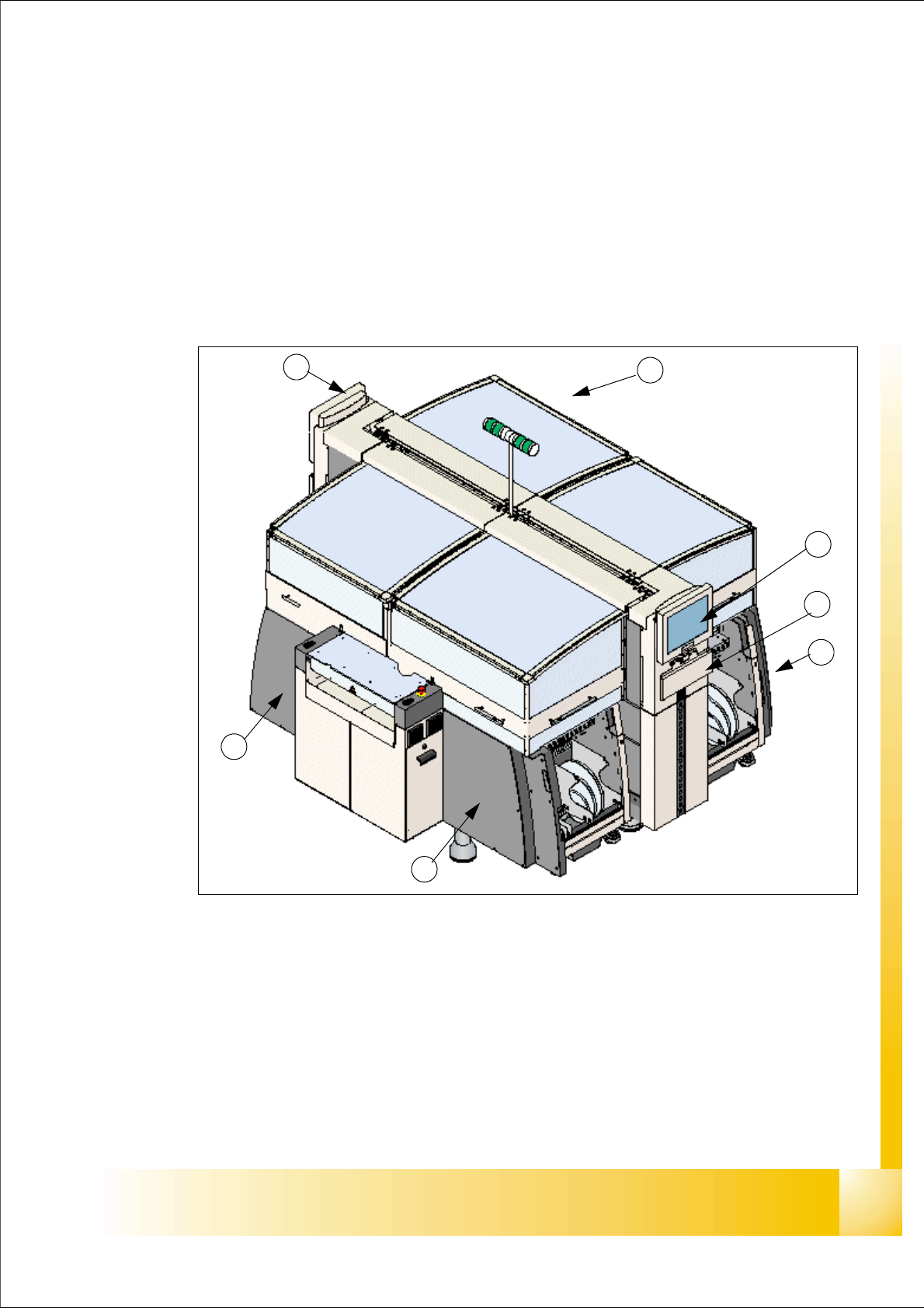
Das SMD Bestückungssystem SIPLACE HF/HF3 (High Flexibility) zeichnet sich durch seine Kon-
figuration, für größtmögliche Präzision und durch hohe Flexibilität aus. Die Maschine bestückt das
gesamte Spektrum der SMD-Bauelemente.
Abb. 2.1 - 1 Überblick Siplace HF/HF3 (ursprüngliche Ausführung)
Legende:
(1) Monitor (auf beiden Seiten) (2) Tastatur (auf beiden Seiten)
(3) Sektor 1 (4) Sektor 2
(5) Sektor 3 (6) Sektor 4
1
1
2
4
3
5
6