CYCLONE-User-Manual.pdf - 第19页
User Manual For Cyclone LC Programmers 19 Figure 3-2: Cyclone LC Right Side View 3.5 Cyclone System Power The Cyclone LC programmer requires a regulated 6V DC Center Positive power supply with 2.5/ 5.5mm female plug. Cyc…
User Manual For Cyclone LC Programmers 18
3 CYCLONE LC HARDWARE
The following is an overview of the features and interfaces of Cyclone LC programmers. Many of
these interfaces are labeled on the underside of the plastic case.
Figure 3-1: Cyclone LC Top View
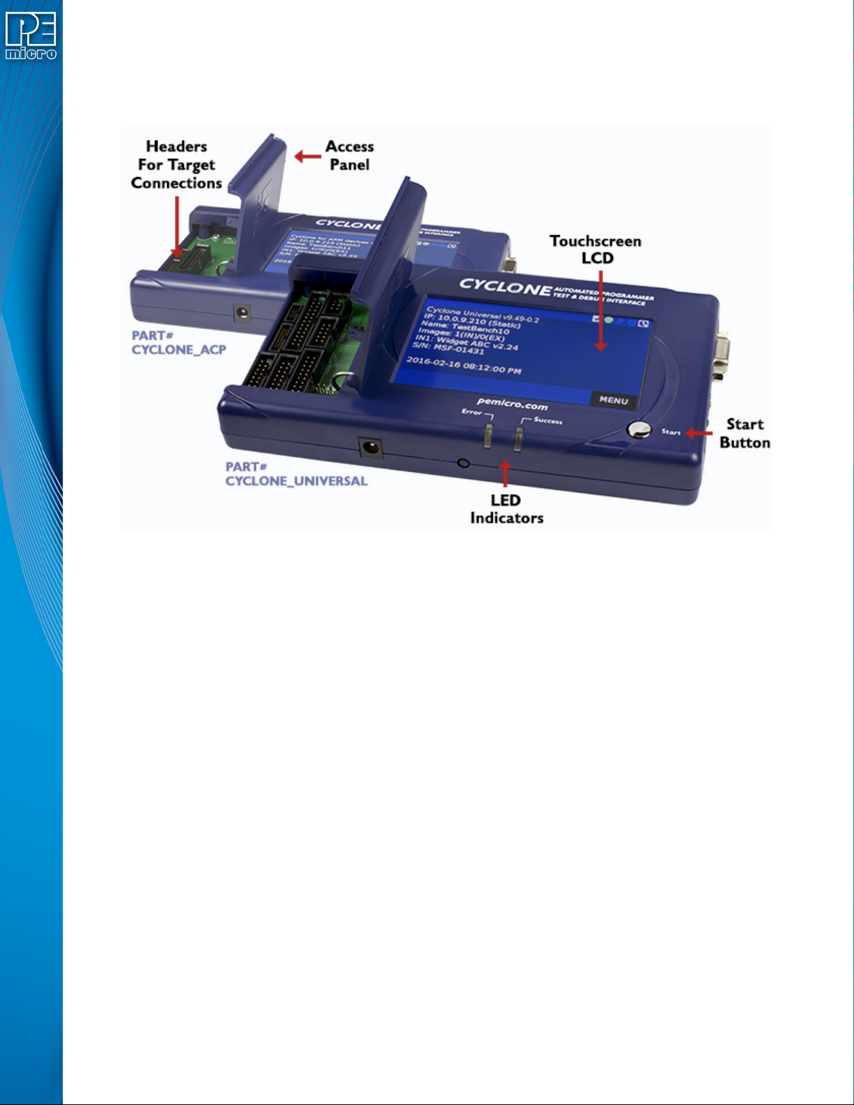
3.1 Touchscreen LCD
The LCD Touchscreen displays information about the Cyclone’s configuration and the
programming process, and also allows the user to navigate the Cyclone’s menus. The location of
the Touchscreen LCD is shown in Figure 3-1.
3.2 LED Indicators
The LED indicators for Error or Success will illuminate depending on the results of the
programming process and provide a clear visual indication of the results. The location of the LED
Indicators is shown in Figure 3-1.
3.3 Start Button
The Start Button can be used to begin the programming process manually, provided that the
Cyclone is properly configured. The location of the Start Button is shown in Figure 3-1.
3.4 Access Panel
The Access Panel can easily be opened to allow the user to connect/disconnect ribbon cables
from the headers, or to configure the Cyclone’s Power Jumpers to select one of the available
Power Management setups. The location of the Access Panel is shown in Figure 3-1; a layout of
the headers and jumpers beneath the Access Panel is shown in Figure 3-5.
User Manual For Cyclone LC Programmers 19
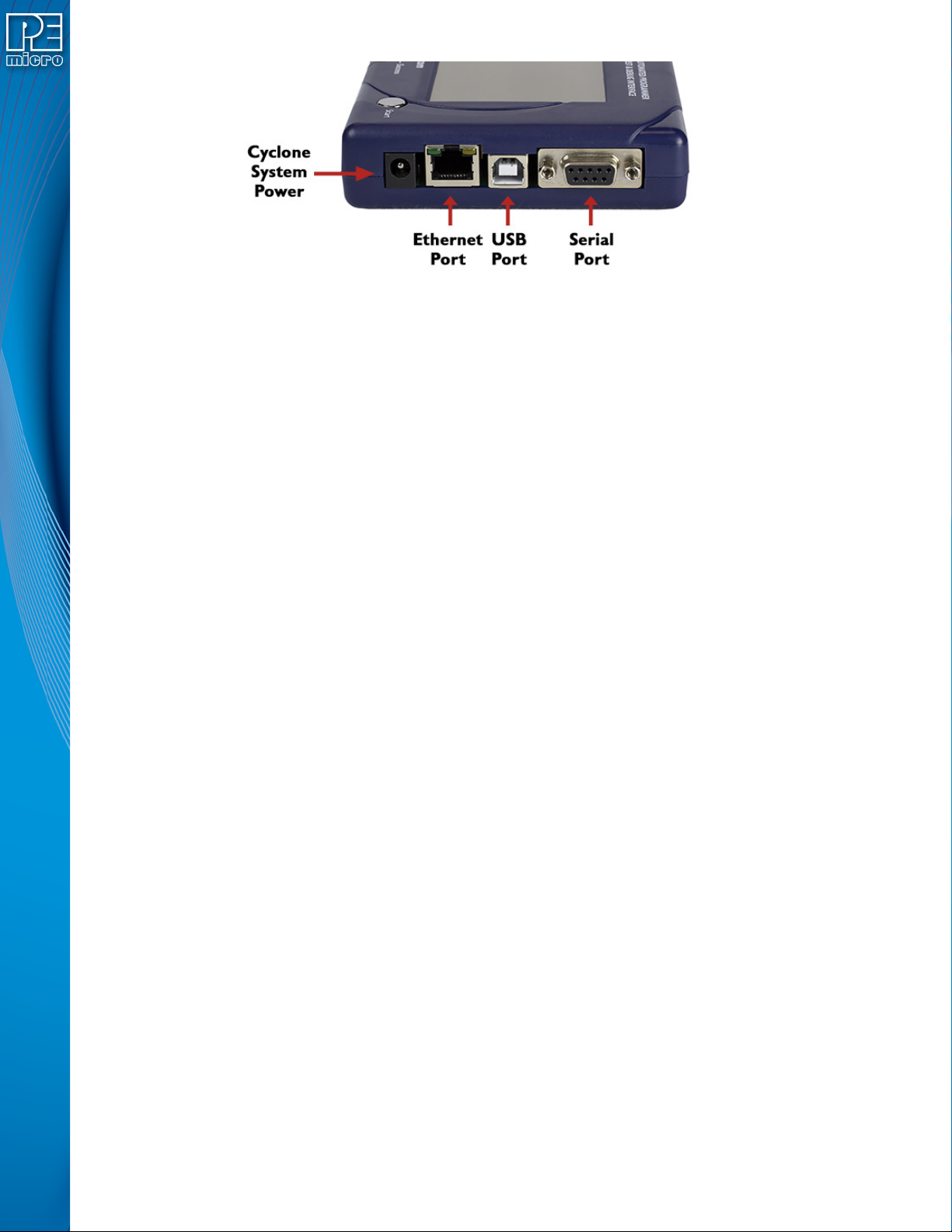
Figure 3-2: Cyclone LC Right Side View
3.5 Cyclone System Power
The Cyclone LC programmer requires a regulated 6V DC Center Positive power supply with 2.5/
5.5mm female plug. Cyclones derive power from the Power Jack located on the right end of the
unit. The location of Cyclone System Power is shown in Figure 3-2.
3.6 RS232 Communication (Serial Port)
The Cyclone LC provides a DB9 Female connector to communicate with a host computer through
the RS232 communication (115200 Baud, 8 Data bits, No parity, 1 Stop bit). The location of the
Serial Port is shown in Figure 3-2.
3.7 Ethernet Communication
The Cyclone LC provides a standard RJ45 socket to communicate with a host computer through
the Ethernet Port (10/100 BaseT). The location of the Ethernet Port is shown in Figure 3-2.
3.8 USB Communications
The Cyclone LC provides a USB connector for Universal Serial Bus communications between the
Cyclone and the host computer. The Cyclone LC is a USB 2.0 Full-Speed compliant device. The
location of the USB Port is shown in Figure 3-2.
3.9 Electromechanical Relays
Inside the Cyclone LC programmer, two electromechanical relays are used to cycle target power.
The specifications of the relays are as following:
Maximum switched power: 30W or 125 VA
Maximum switched current: 1A
Maximum switched voltage: 150VDC or 300VAC
UL Rating: 1A at 30 VDC
1A at 125 VAC
PEmicro only recommends switching DC voltages up to 24 Volts.
User Manual For Cyclone LC Programmers 20
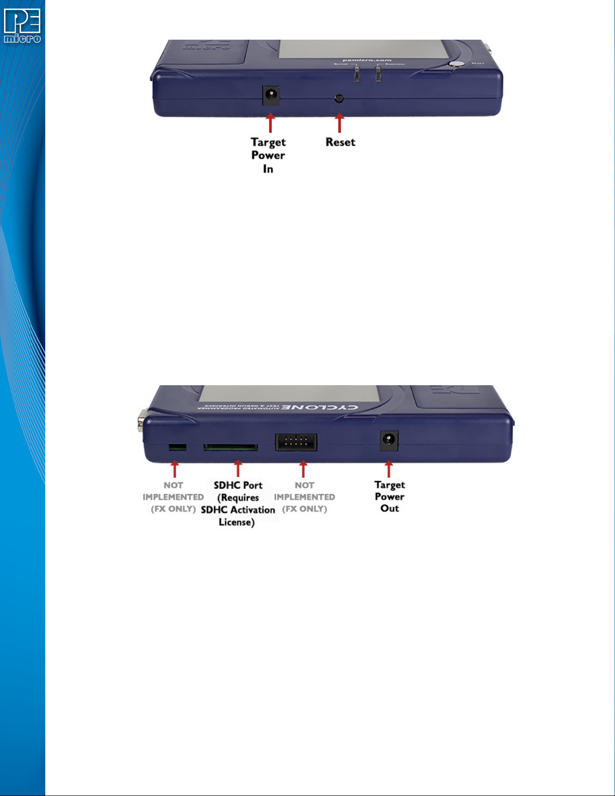
Figure 3-3: Cyclone LC Front Side View
3.10 Power Connectors
The Cyclone LC programmers provide a Target Power Supply Input Jack and a Target Power
Supply Output Jack with 2.5/5.5 mm Pin Diameter. The power jacks are connected or
disconnected by two electromechanical relays. When connected, the Center Pin of the Target
Power Supply Input Jack is connected to the Center Pin of the Target Power Supply Output Jack.
When disconnected, both terminals of the Target Power Supply Output Jack are connected to
GND via a 1W, 100 Ohm resistor. The location of Target Power In is shown in Figure 3-3, and the
location of Target Power Out is shown in Figure 3-3.
3.11 Reset Button
The Reset Button performs a hard reset of the Cyclone system. The location of the Reset Button is
shown in Figure 3-3.
Figure 3-4: Cyclone LC Rear Side View
3.12 SDHC Port
Note: The SDHC port is activated on all Cyclone FX programmers, and may be activated on Cyclone
LC programmers via purchase of the SDHC Port Activation License.
The SDHC port allows the user to store programming images that are, individually or collectively,
larger than the Cyclone’s internal memory. It also makes it quicker and more convenient to swap
programming images. PEmicro offers certified SDHC cards on our website at pemicro.com. The
location of the SDHC Port is shown in Figure 3-4.
Programming images are managed on the SD card in exactly the same way as they are in the
Cyclone’s internal memory. Please see Section 6.2 - Managing Multiple SAP Images for more
information about using the Manage Images utility.
Note: To view detailed information about the status of the SDHC card/port, tap the icon bar at the top of
the touchscreen menu. This status can provide you with relevant information if you are