CYCLONE-User-Manual.pdf - 第22页
User Manual For Cyclone LC Programmers 22 Figure 3-5: T arget Headers & Power Jumpers ( CYCLONE-LC-UNIV vs. CYCLONE-LC-ARM ) Mechanical drawings are shown below whose dimensions are representative of the pin size and…

User Manual For Cyclone LC Programmers 21
encountering any difficulty while trying to use an SDHC card.
3.13 Optional Oscillator (MON08 Only)
Cyclone LC programmers with MON08 support (PEmicro Part# CYCLONE-LC-UNIV only)
provide a software configurable 9.8304MHz or 4.9152 MHz oscillator clock signal to Pin 13 of the
MON08 Connector. The user may use this clock signal to overdrive the target RC or crystal
circuitry. If this signal is not used, just leave Pin 13 of the target MON08 header unconnected.
Please note that if the target already uses an oscillator as its clock, the Cyclone will NOT be able to
overdrive it. The clock should have sufficient drive to be used with a target system even if the
target system has an RC circuit or crystal connected.
3.14 Cyclone Time / Real Time Clock
Cyclone LC programmers are equipped with a Real Time Clock (RTC) module designed to keep
accurate timing even when the Cyclone is turned off.
The Date & Time are displayed on the home screen. Date/Time settings can be configured by
navigating to the following menu using the touchscreen display:
Main Menu / Configure Cyclone Settings / Configure Time Settings
For more information on the available configuration options, see Section 5.2.3.3 - Configure
Time Settings (Cyclone Time / Real Time Clock).
3.15 Power Jumper Settings
The Power Jumpers must be set differently for various power management options that the
Cyclone LC offers. If the target is being powered independently of the Cyclone LC, all pins in the
Power Jumpers header must instead be left unpopulated. To reveal the Power Jumpers header, lift
the access panel on the left end of the Cyclone LC. The location is indicated as Power Jumpers in
Figure 3-5. Please see CHAPTER 4 - TARGET POWER MANAGEMENT for the correct jumper
settings for the Cyclone’s power management options. A quick guide to these settings is also
located on the underside label of the Cyclone LC.
3.16 Debug Connectors
When purchasing a Cyclone LC programmer, the user is able to choose between two part
numbers, each corresponding to a different level of device support. See the sticker on the
underside of the Cyclone to determine the PEmicro part# for your specific Cyclone LC
programmer.
PEmicro Part# CYCLONE-LC-ARM supports ARM Cortex devices only, so this programmer
provides one shrouded, un-keyed, 0.100-inch pitch dual row 0.025-inch square header, and two
shrouded, keyed 0.050-inch pitch dual row mini headers.
PEmicro Part# CYCLONE-LC-UNIV supports ARM Cortex devices and additionally supports
target connections to many 8-/16-/32-bit NXP architectures, so this programmer provides six
shrouded, un-keyed, 0.100-inch pitch dual row 0.025-inch square headers, and two shrouded,
keyed 0.050-inch pitch dual row mini headers.
To reveal the headers and connect/disconnect ribbon cables, lift the access panel on the left end
of the Cyclone. Each header is designated for one or more specific target architectures, as
indicated in Figure 3-5.
User Manual For Cyclone LC Programmers 22
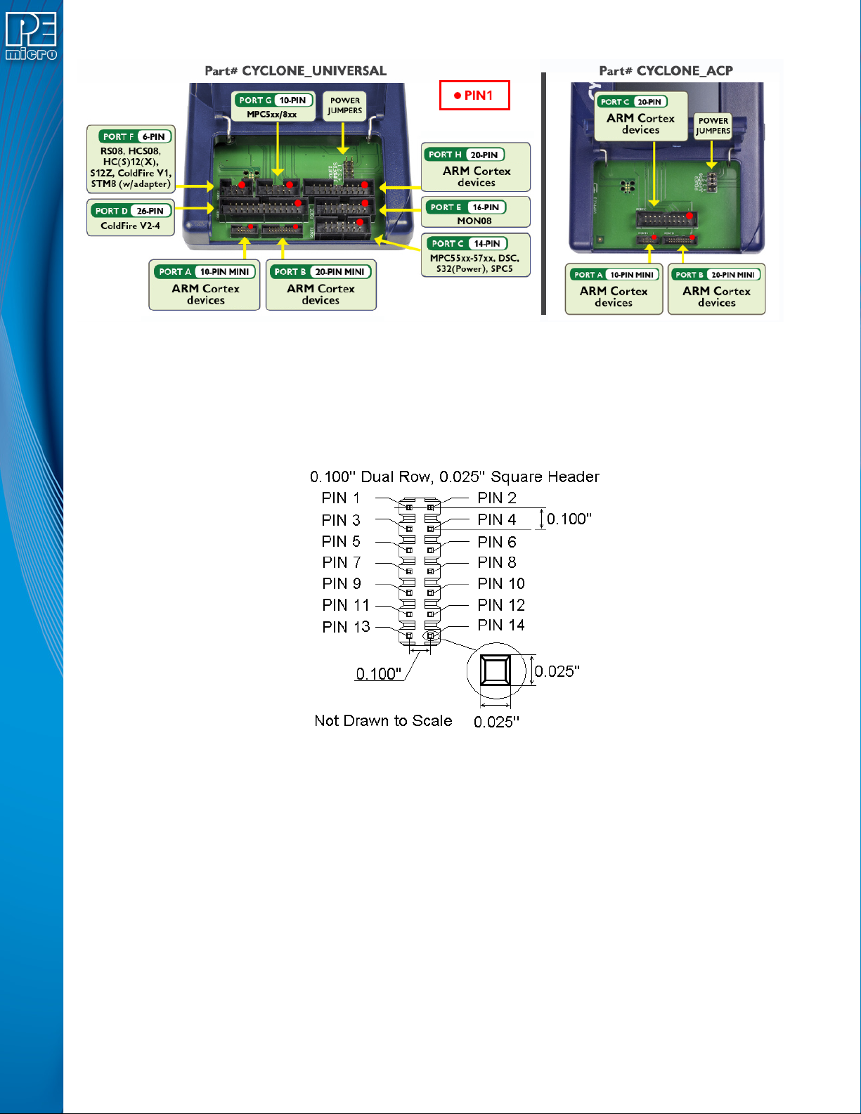
Figure 3-5: Target Headers & Power Jumpers (CYCLONE-LC-UNIV vs.CYCLONE-LC-ARM)
Mechanical drawings are shown below whose dimensions are representative of the pin size and
spacing of these headers.
Note: The number of pins depicted in the mechanical drawings may differ from the Cyclone headers; the
drawings are provided simply to demonstrate pin size and spacing.
Figure 3-6: 20-Pin Un-Keyed Header Dimensions
User Manual For Cyclone LC Programmers 23
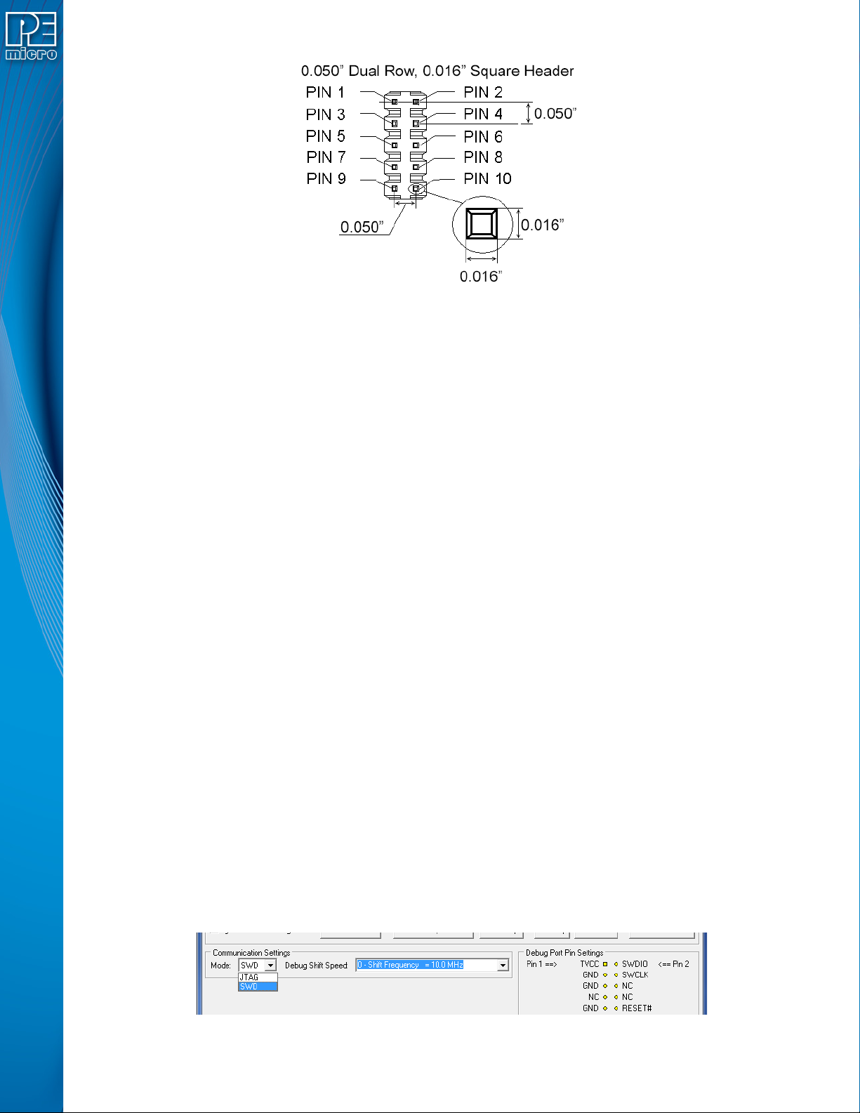
Figure 3-7: Mini 10-Pin and Mini 20-Pin Keyed Header Dimensions
3.17 Target Headers For Part# CYCLONE-LC-ARM
PEmicro Part# CYCLONE-LC-ARM features 3 ports labeled A-C.
3.17.1 PORT A: 10-Pin Keyed Mini Connector (Kinetis, S32 (ARM), other PEmicro-Supported ARM
devices)
3.17.1.1 JTAG Pin Assignments
The Cyclone provides a keyed 10-pin 0.050-inch pitch double row connector for ARM targets. The
location of the this header is indicated as PORT A in Figure 3-5. The 10-pin keyed mini connector
pin definitions for JTAG mode are as follows:
10-Pin Keyed Mini Connector JTAG Mode Pin Assignments
PIN 1 - TVCC TMS - PIN 2
PIN 3 - GND TCK - PIN 4
PIN 5 - GND TDO - PIN 6
PIN 7 - NC TDI - PIN 8
PIN 9 - NC* RESET - PIN 10
Note: *The pin is reserved for internal use within the PEmicro interface.
Cyclone LC programmers also support SWD Mode. This replaces the JTAG connection with a
clock and single bi-directional data pin.
3.17.1.2 SWD Mode Pin Assignments
10-Pin Keyed Mini Connector SWD Mode Pin Assignments
PIN 1 - TVCC TMS/SWDIO - PIN 2
PIN 3 - GND TCK/SWCLK - PIN 4
PIN 5 - GND NC* - PIN 6
PIN 7 - NC NC* - PIN 8
PIN 9 - NC* RESET - PIN 10
Note: *The pin is reserved for internal use within the PEmicro interface.
SWD Mode is selected from the “Communication Mode” drop-down box in the Cyclone Image
Creation Utility:
Figure 3-8: Communications Mode Selection