CYCLONE-User-Manual.pdf - 第20页
User Manual For Cyclone LC Programmers 20 Figure 3-3: Cyclone LC Front Side View 3.10 Power Connectors The Cyclone LC programmers provide a T arget Power Supply Input Jack and a T arget Power Supply Output Jack with 2.5/…
User Manual For Cyclone LC Programmers 19
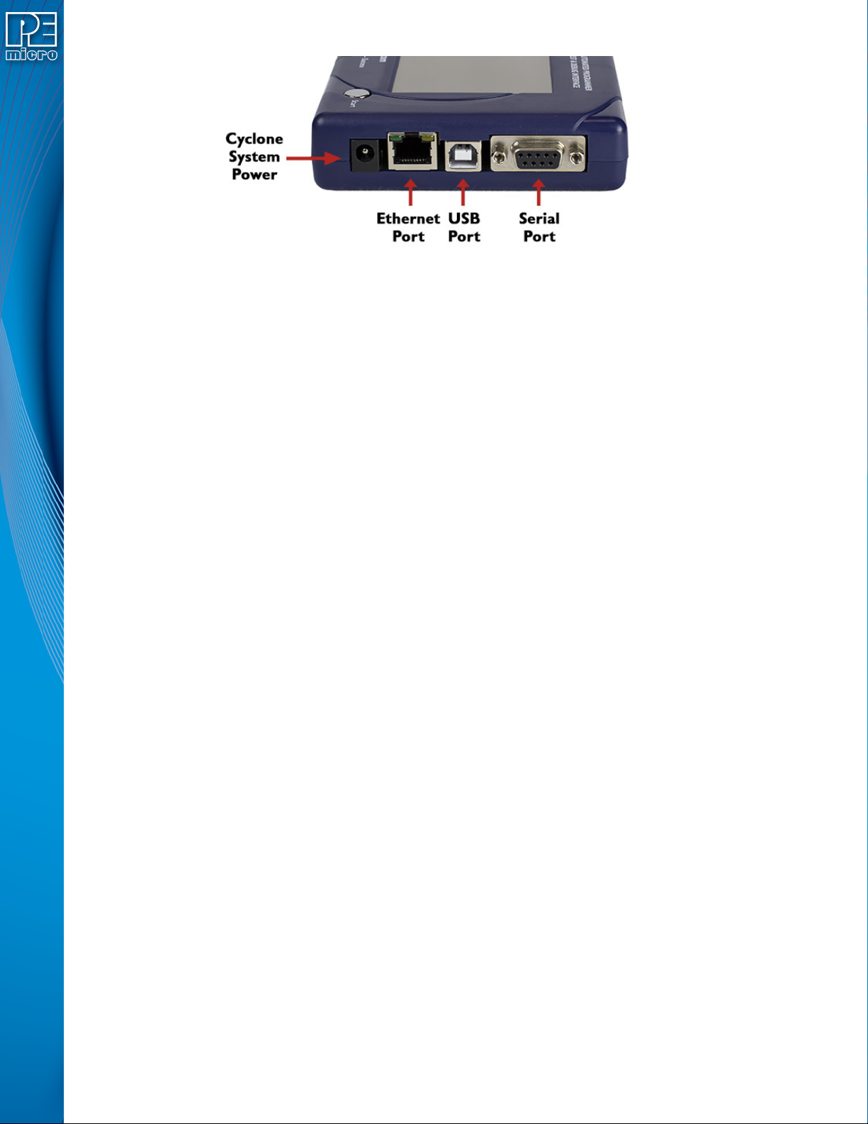
Figure 3-2: Cyclone LC Right Side View
3.5 Cyclone System Power
The Cyclone LC programmer requires a regulated 6V DC Center Positive power supply with 2.5/
5.5mm female plug. Cyclones derive power from the Power Jack located on the right end of the
unit. The location of Cyclone System Power is shown in Figure 3-2.
3.6 RS232 Communication (Serial Port)
The Cyclone LC provides a DB9 Female connector to communicate with a host computer through
the RS232 communication (115200 Baud, 8 Data bits, No parity, 1 Stop bit). The location of the
Serial Port is shown in Figure 3-2.
3.7 Ethernet Communication
The Cyclone LC provides a standard RJ45 socket to communicate with a host computer through
the Ethernet Port (10/100 BaseT). The location of the Ethernet Port is shown in Figure 3-2.
3.8 USB Communications
The Cyclone LC provides a USB connector for Universal Serial Bus communications between the
Cyclone and the host computer. The Cyclone LC is a USB 2.0 Full-Speed compliant device. The
location of the USB Port is shown in Figure 3-2.
3.9 Electromechanical Relays
Inside the Cyclone LC programmer, two electromechanical relays are used to cycle target power.
The specifications of the relays are as following:
Maximum switched power: 30W or 125 VA
Maximum switched current: 1A
Maximum switched voltage: 150VDC or 300VAC
UL Rating: 1A at 30 VDC
1A at 125 VAC
PEmicro only recommends switching DC voltages up to 24 Volts.
User Manual For Cyclone LC Programmers 20
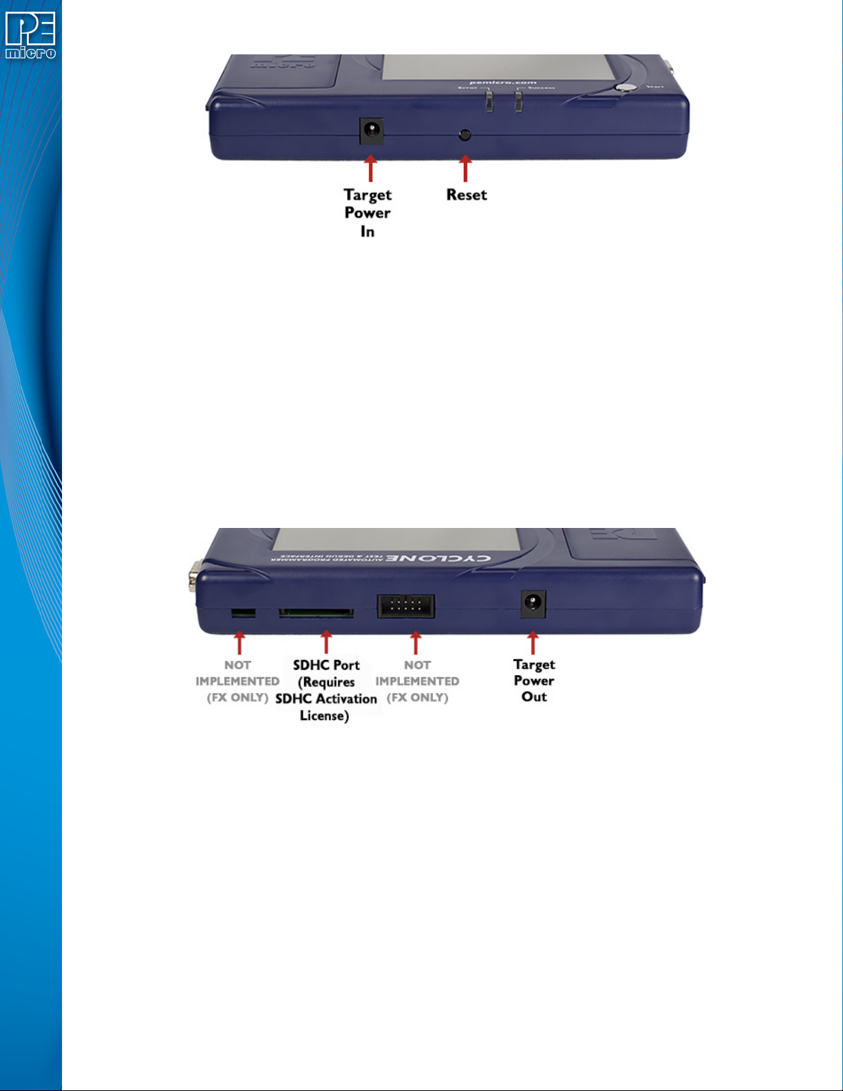
Figure 3-3: Cyclone LC Front Side View
3.10 Power Connectors
The Cyclone LC programmers provide a Target Power Supply Input Jack and a Target Power
Supply Output Jack with 2.5/5.5 mm Pin Diameter. The power jacks are connected or
disconnected by two electromechanical relays. When connected, the Center Pin of the Target
Power Supply Input Jack is connected to the Center Pin of the Target Power Supply Output Jack.
When disconnected, both terminals of the Target Power Supply Output Jack are connected to
GND via a 1W, 100 Ohm resistor. The location of Target Power In is shown in Figure 3-3, and the
location of Target Power Out is shown in Figure 3-3.
3.11 Reset Button
The Reset Button performs a hard reset of the Cyclone system. The location of the Reset Button is
shown in Figure 3-3.
Figure 3-4: Cyclone LC Rear Side View
3.12 SDHC Port
Note: The SDHC port is activated on all Cyclone FX programmers, and may be activated on Cyclone
LC programmers via purchase of the SDHC Port Activation License.
The SDHC port allows the user to store programming images that are, individually or collectively,
larger than the Cyclone’s internal memory. It also makes it quicker and more convenient to swap
programming images. PEmicro offers certified SDHC cards on our website at pemicro.com. The
location of the SDHC Port is shown in Figure 3-4.
Programming images are managed on the SD card in exactly the same way as they are in the
Cyclone’s internal memory. Please see Section 6.2 - Managing Multiple SAP Images for more
information about using the Manage Images utility.
Note: To view detailed information about the status of the SDHC card/port, tap the icon bar at the top of
the touchscreen menu. This status can provide you with relevant information if you are

User Manual For Cyclone LC Programmers 21
encountering any difficulty while trying to use an SDHC card.
3.13 Optional Oscillator (MON08 Only)
Cyclone LC programmers with MON08 support (PEmicro Part# CYCLONE-LC-UNIV only)
provide a software configurable 9.8304MHz or 4.9152 MHz oscillator clock signal to Pin 13 of the
MON08 Connector. The user may use this clock signal to overdrive the target RC or crystal
circuitry. If this signal is not used, just leave Pin 13 of the target MON08 header unconnected.
Please note that if the target already uses an oscillator as its clock, the Cyclone will NOT be able to
overdrive it. The clock should have sufficient drive to be used with a target system even if the
target system has an RC circuit or crystal connected.
3.14 Cyclone Time / Real Time Clock
Cyclone LC programmers are equipped with a Real Time Clock (RTC) module designed to keep
accurate timing even when the Cyclone is turned off.
The Date & Time are displayed on the home screen. Date/Time settings can be configured by
navigating to the following menu using the touchscreen display:
Main Menu / Configure Cyclone Settings / Configure Time Settings
For more information on the available configuration options, see Section 5.2.3.3 - Configure
Time Settings (Cyclone Time / Real Time Clock).
3.15 Power Jumper Settings
The Power Jumpers must be set differently for various power management options that the
Cyclone LC offers. If the target is being powered independently of the Cyclone LC, all pins in the
Power Jumpers header must instead be left unpopulated. To reveal the Power Jumpers header, lift
the access panel on the left end of the Cyclone LC. The location is indicated as Power Jumpers in
Figure 3-5. Please see CHAPTER 4 - TARGET POWER MANAGEMENT for the correct jumper
settings for the Cyclone’s power management options. A quick guide to these settings is also
located on the underside label of the Cyclone LC.
3.16 Debug Connectors
When purchasing a Cyclone LC programmer, the user is able to choose between two part
numbers, each corresponding to a different level of device support. See the sticker on the
underside of the Cyclone to determine the PEmicro part# for your specific Cyclone LC
programmer.
PEmicro Part# CYCLONE-LC-ARM supports ARM Cortex devices only, so this programmer
provides one shrouded, un-keyed, 0.100-inch pitch dual row 0.025-inch square header, and two
shrouded, keyed 0.050-inch pitch dual row mini headers.
PEmicro Part# CYCLONE-LC-UNIV supports ARM Cortex devices and additionally supports
target connections to many 8-/16-/32-bit NXP architectures, so this programmer provides six
shrouded, un-keyed, 0.100-inch pitch dual row 0.025-inch square headers, and two shrouded,
keyed 0.050-inch pitch dual row mini headers.
To reveal the headers and connect/disconnect ribbon cables, lift the access panel on the left end
of the Cyclone. Each header is designated for one or more specific target architectures, as
indicated in Figure 3-5.