CYCLONE-User-Manual.pdf - 第23页
User Manual For Cyclone LC Programmers 23 Figure 3-7: Mini 10-Pin and Mini 20-Pin Keyed Header Dimensions 3.17 T arget Headers For Part# CYCLONE-LC-ARM PEmicro Part# CYCLONE-LC-ARM features 3 ports labeled A-C. 3.17.1 PO…
User Manual For Cyclone LC Programmers 22
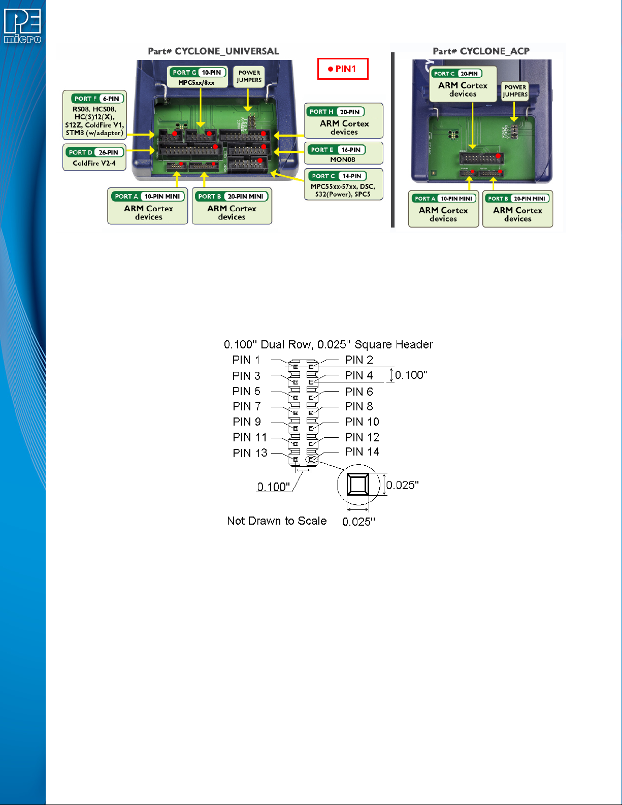
Figure 3-5: Target Headers & Power Jumpers (CYCLONE-LC-UNIV vs.CYCLONE-LC-ARM)
Mechanical drawings are shown below whose dimensions are representative of the pin size and
spacing of these headers.
Note: The number of pins depicted in the mechanical drawings may differ from the Cyclone headers; the
drawings are provided simply to demonstrate pin size and spacing.
Figure 3-6: 20-Pin Un-Keyed Header Dimensions
User Manual For Cyclone LC Programmers 23
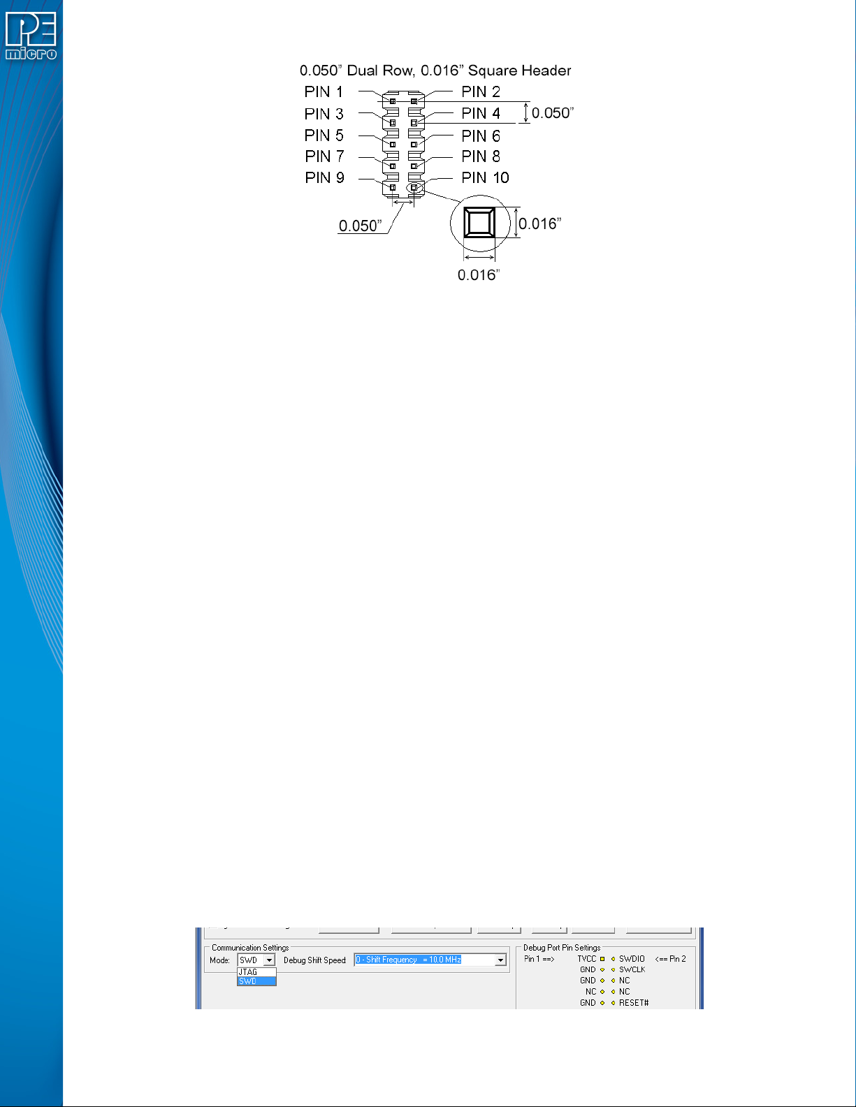
Figure 3-7: Mini 10-Pin and Mini 20-Pin Keyed Header Dimensions
3.17 Target Headers For Part# CYCLONE-LC-ARM
PEmicro Part# CYCLONE-LC-ARM features 3 ports labeled A-C.
3.17.1 PORT A: 10-Pin Keyed Mini Connector (Kinetis, S32 (ARM), other PEmicro-Supported ARM
devices)
3.17.1.1 JTAG Pin Assignments
The Cyclone provides a keyed 10-pin 0.050-inch pitch double row connector for ARM targets. The
location of the this header is indicated as PORT A in Figure 3-5. The 10-pin keyed mini connector
pin definitions for JTAG mode are as follows:
10-Pin Keyed Mini Connector JTAG Mode Pin Assignments
PIN 1 - TVCC TMS - PIN 2
PIN 3 - GND TCK - PIN 4
PIN 5 - GND TDO - PIN 6
PIN 7 - NC TDI - PIN 8
PIN 9 - NC* RESET - PIN 10
Note: *The pin is reserved for internal use within the PEmicro interface.
Cyclone LC programmers also support SWD Mode. This replaces the JTAG connection with a
clock and single bi-directional data pin.
3.17.1.2 SWD Mode Pin Assignments
10-Pin Keyed Mini Connector SWD Mode Pin Assignments
PIN 1 - TVCC TMS/SWDIO - PIN 2
PIN 3 - GND TCK/SWCLK - PIN 4
PIN 5 - GND NC* - PIN 6
PIN 7 - NC NC* - PIN 8
PIN 9 - NC* RESET - PIN 10
Note: *The pin is reserved for internal use within the PEmicro interface.
SWD Mode is selected from the “Communication Mode” drop-down box in the Cyclone Image
Creation Utility:
Figure 3-8: Communications Mode Selection
User Manual For Cyclone LC Programmers 24
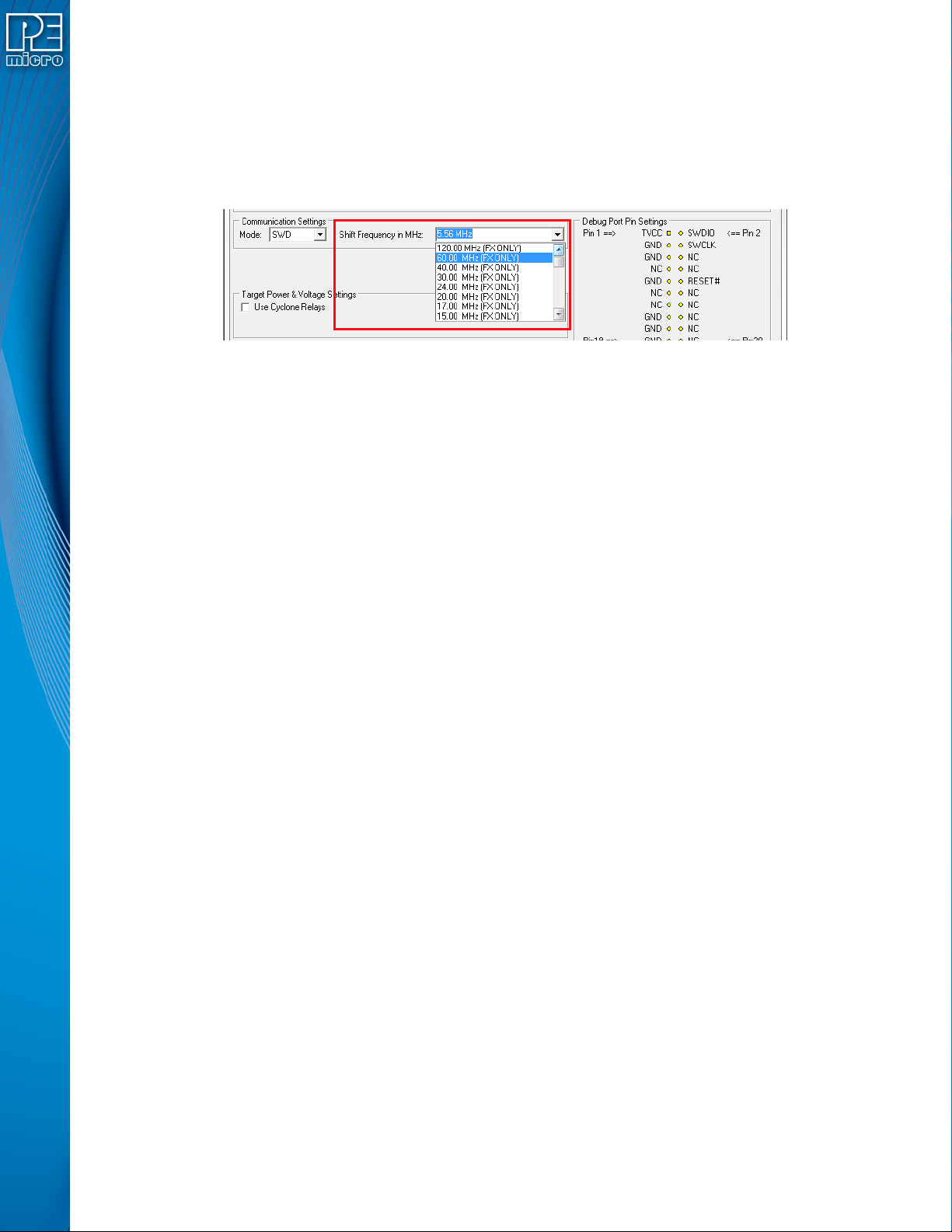
3.17.1.2.1 High-Performance Communications (FX ONLY)
If high-performance options are available for the selected device they will appear in the “Shift
Frequency in MHz” drop-down. Cyclone FX programmers are capable of high-performance
communications when using certain ARM Cortex targets in SWD mode.
Note: Cyclone LC programmers cannot currently take advantage of high-performance options, although
the frequencies appear in the display.
Figure 3-9: High-Performance Options (FX ONLY)
3.17.2 PORT B: 20-Pin Keyed Mini Connector (Kinetis, S32 (ARM), other PEmicro-Supported ARM
devices)
3.17.2.1 JTAG Mode Pin Assignments
The Cyclone provides a keyed 20-pin 0.050-inch pitch double row connector for ARM targets. The
location of the this header is indicated as PORT B in Figure 3-5. The 20-pin keyed mini connector
pin definitions for JTAG mode are as follows:
20-Pin Keyed Mini Connector JTAG Mode Pin Assignments
PIN 1 - TVCC TMS - PIN 2
PIN 3 - GND TCK - PIN 4
PIN 5 - GND TDO - PIN 6
PIN 7 - NC TDI - PIN 8
PIN 9 - NC* RESET - PIN 10
PIN 11 - NC NC* - PIN 12
PIN 13 - NC NC* - PIN 14
PIN 15 - GND NC* - PIN 16
PIN 17 - GND NC* - PIN 18
PIN 19 - GND NC* - PIN 20
Note: *The pin is reserved for internal use within the PEmicro interface.
3.17.2.2 SWD Mode Pin Assignments
Cyclone LC programmers also support SWD Mode. This replaces the JTAG connection with a
clock and single bi-directional data pin.
20-Pin Keyed Mini Connector SWD Mode Pin Assignments
PIN 1 - TVCC TMS/SWDIO - PIN 2
PIN 3 - GND TCK/SWCLK - PIN 4
PIN 5 - GND NC* - PIN 6
PIN 7 - NC NC* - PIN 8
PIN 9 - NC* RESET - PIN 10
PIN 11 - NC NC* - PIN 12
PIN 13 - NC NC* - PIN 14
PIN 15 - GND NC* - PIN 16
PIN 17 - GND NC* - PIN 18
PIN 19 - GND NC* - PIN 20
Note: *The pin is reserved for internal use within the PEmicro interface.