CYCLONE-User-Manual.pdf - 第65页
User Manual For Cyclone LC Programmers 65 12. 7.4 Status Window The status window appears in the lower left corner of the home screen and displays the results of programming operations. 7.4.1 Error Information Icon When …
User Manual For Cyclone LC Programmers 64
7.2 Operation Via LCD Touchscreen Menu
Once the Cyclone LC is configured for stand-alone programming it may be operated by making
selections from the touchscreen LCD menu. This section describes the menu functions that allow
the user to easily execute stand-alone programming functions using the touchscreen LCD.
7.3 Home Screen
The home screen appears when the Cyclone is powered on, or when the Home button
is tapped.
7.3.1 Icons
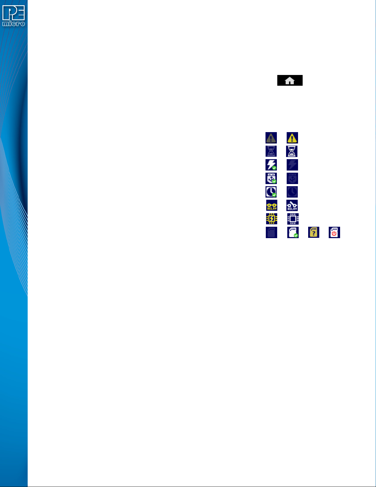
A row of icons in the upper right corner indicates the status of various attributes of the Cyclone.
Note: The user may tap on the row of icons to view the meaning of each of the currently displayed icons.
Cyclone Unit Status: Ok / Bad
Programming Status: Ready / Busy
Target Power Relays: On / Off
USB-To-PC Enumerated: Yes / No
Real-Time clock Enabled & Working: Yes / No
Cyclone Power Relays: Closed / Open
Target Device Is Powered*: Yes / No
SDHC Memory Card: None / Valid / Unformattted / Reset Cyclone**
* Target Device Is Powered - “Yes” indicates that the Cyclone LC detects power on the Vcc pin of
the target device programming header.
** SDHC Memory Card (Requires SDHC License Activation) - “Reset Cyclone” indicates that the
Cyclone needs to be reset before the SDHC card will register as Valid. The user can push the
Reset button which is located on the front side of the Cyclone, below the LED indicators.
7.3.2 Configurable Display Area
The main area of the home screen can be configured to optionally display the following
information, by using the Cyclone IP Configuration Utility (see Section 5.2.3.5.4 - Configure
Home Screen):
1. Firmware version of the Cyclone (always shown).
2. IP address assigned to the Cyclone.
3. Name assigned to the Cyclone.
4. Number of programming images in the Cyclone’s memory.
5. Name of the selected programming image.
6. First serial number associated with the selected image
7. Current status.
8. Results of the last operation performed.
9. Time and date.
10. Status Window and Main Menu button (always shown).
11. Programming count & limit
User Manual For Cyclone LC Programmers 65
12.
7.4 Status Window
The status window appears in the lower left corner of the home screen and displays the results of
programming operations.
7.4.1 Error Information Icon
When the Cyclone experiences an error during programming operations, the Info icon will appear
to the left of the Menu button (or AUX button, if configured).
Info Icon:
Press the Info icon to view a detailed description of the error.
7.4.2 AUX Button (Appears If Configured)
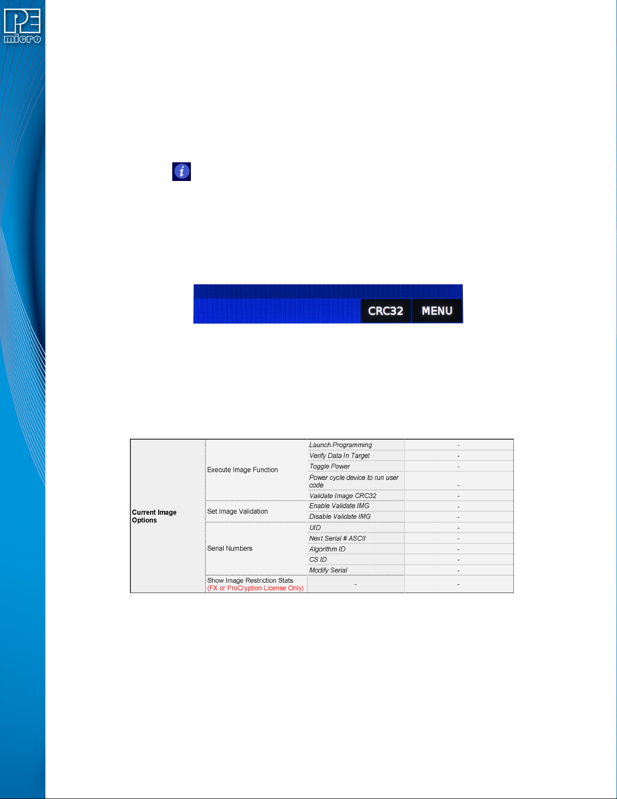
The Cyclone allows the user to add an Auxiliary (AUX) button to the home screen which will
perform a specific function when pressed. The specific function is chosen by the user when the
AUX button is configured. The AUX button will appear on the home screen to the left of the “Menu”
button, in the lower right corner of the home screen.
Figure 7-1: AUX Button On Home Screen (configured for perform CRC32 function)
For information on how to configure the AUX button, see Section 5.2.4 - Status.
7.4.3 Main Menu
The Main Menu is accessible by pressing the “Menu” button when the Home Screen is displayed.
The Main Menu screen contains four selections. From these, select “Current Image Options.”
Figure 7-2: Touchscreen LCD Menu - Standalone Functions Highlighted
The menu selections in “Current Image Options” will allow the user to execute programming
operations, verify data, toggle power, validate the programming image, and modify the upcoming
serial number if necessary.
7.4.3.1 Execute Image Function
Execute Specific SAP Function presents four Stand-Alone Programming functions that you may
execute by tapping the function that you wish to execute:
User Manual For Cyclone LC Programmers 66
7.4.3.1.1 Launch Programming
This allows the user to execute the programming function. The Cyclone will program the target
device, if able, using the currently selected programming image. This is functionally equivalent to
pressing the Start button.
7.4.3.1.2 Verify Data In Target
Performs a verify function on the data that has been programmed into the target device.
7.4.3.1.3 Toggle Power
Toggles the target power and makes sure all ports are driven to debug mode level.
7.4.3.1.4 Power Cycle Device To Run User Code
Toggles the target power and maintains tri-state mode for all signals.
7.4.3.1.5 Validate Image CRC32
Allows the user to perform a CRC32 validation on the currently selected programming image.
7.4.3.2 Set Image Validation
Allows the user to choose between two validation settings: 1) validate the image each time the
Start button is pressed, or 2) do not validate the image.
7.4.3.3 Serial Numbers
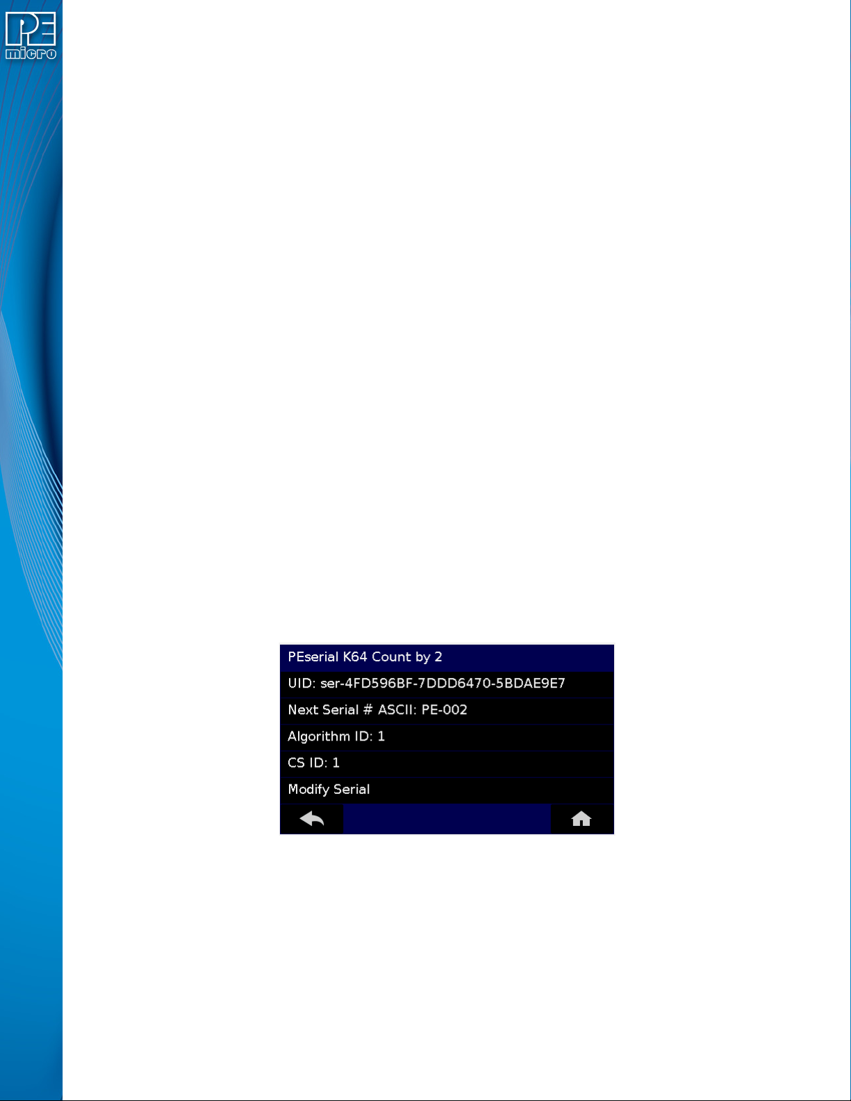
Displays the serial number information associated with the currently selected programming image.
If there is none, it will display, “This Image Contains No Serial Numbers.” There may be one or
more Serial Files associated with the image. The user can click on a specific Serial File name to
see the following information about that Serial File:
• UID - Unique identifier of the serial number
• Next Serial # ASCII - Next serial number to be programmed (shown in ASCII format)
• Algorithm ID - Displays the algorithm ID of the serial file
• CS ID - Displays the ID of the CS (Choose Serial) command in the SAP file.
Figure 7-3: Serial File Selection
The user can also click on “Modify Serial Number” to edit that serial number. It is possible to
Decrease or Increase the Next Serial by -10, -1, +1, +10. This is often done to address issues in
the production process, such as during initial setup.